
Spinning roller frame device

A technology of roll frame and rotating roll, which is applied in the field of textile roll frame devices, can solve the problems such as the inconvenience of taking and placing the textile roll frame, and achieve the effect of solving the inconvenience of taking and placing, easy to operate, and convenient to take and place

Inactive Publication Date: 2018-11-13
湖州新爱品纺织有限公司
View PDF1 Cites 0 Cited by
  • Summary
  • Abstract
  • Description
  • Claims
  • Application Information

AI Technical Summary

Problems solved by technology

[0005] Aiming at the deficiencies of the prior art, the present invention provides a textile roller stand device, which solves the problem of inconvenient pick-and-place of the existing textile roller stand

Method used

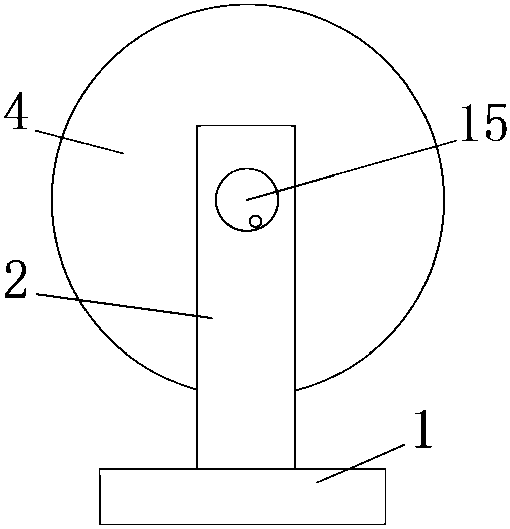
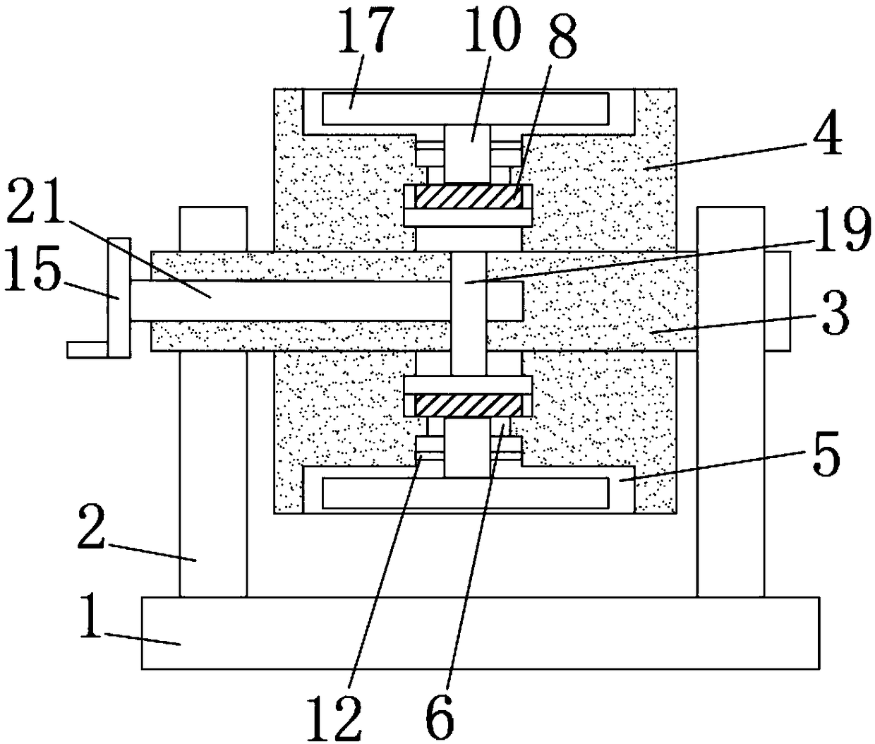
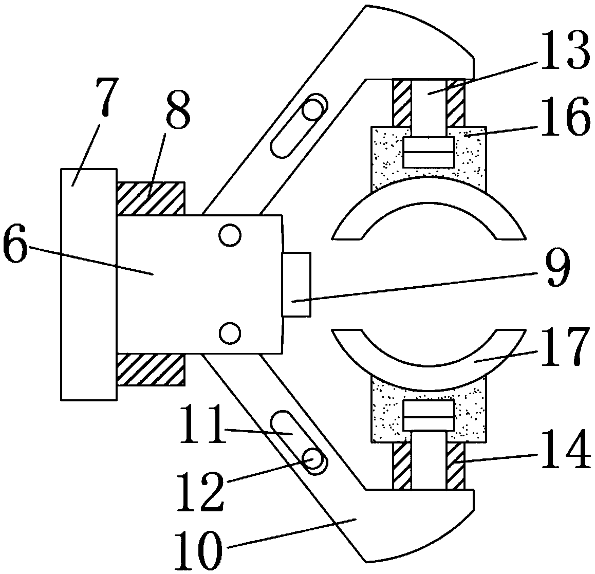

Image

  • Spinning roller frame device
  • Spinning roller frame device
  • Spinning roller frame device

Examples


Embodiment Construction

[0027] The following will clearly and completely describe the technical solutions in the embodiments of the present invention with reference to the accompanying drawings in the embodiments of the present invention. Obviously, the described embodiments are only some, not all, embodiments of the present invention.

[0028] In describing the present invention, it is to be understood that the terms "centre", "length", "width", "thickness", "upper", "lower", "front", "rear", "vertical", The orientation or positional relationship indicated by "horizontal", "top", "bottom", "inner", "outer", "axial", and "circumferential" are based on the orientation or positional relationship shown in the drawings, and are only In order to facilitate the description of the present invention and simplify the description, it does not indicate or imply that the device or element referred to must have a specific orientation, be constructed and operated in a specific orientation, and thus should not be co...


PUM


Abstract

The invention discloses a spinning roller frame device and relates to the technical field of spinning. The spinning roller frame device comprises a base. The two sides of the top end of the base are each fixedly connected with a support column. A first rotary shaft is movably connected to the top ends of the support columns. A rotary roller is movably connected in the axial direction of the firstrotary shaft. A first groove is formed in the rotary roller. An adjusting rod is arranged in the first groove. A limiting block is fixedly connected to one end of the adjusting rod. A return spring isarranged in the middle of the adjusting rod circumferentially. One end of the return spring is fixedly connected with the limiting block. The other end of the return spring is fixedly connected withthe rotary roller. The spinning roller frame device is provided with the rotary roller, and thus spinning rollers can be placed annularly, needed spinning rollers can be selected more easily during taking and placing. The adjusting rod is arranged, thus a force arm can be driven to achieve a clamp opening and closing purpose, and a clamping effect is achieved. The return spring is arranged, thus the adjusting rod can be driven to pull the force arm backwards, and an automatic clamping purpose is achieved. A push block is arranged so that the spinning rollers can be pushed out.

Description

technical field [0001] The invention relates to the technical field of textiles, in particular to a textile roller frame device. Background technique [0002] The original meaning of textile is taken from the general term of spinning and weaving, but with the continuous development and improvement of the textile knowledge system and discipline system, especially after the emergence of non-woven textile materials and three-dimensional composite weaving technologies, the current textile is not only a traditional The hand-spun and weaved fabrics also include clothing, industrial and decorative textiles produced by non-woven technology, modern three-dimensional weaving technology and modern electrostatic nano-netting technology. In the existing textile enterprises, the used textile rolls are usually placed on the textile roll stands, but most of the existing textile roll stands on the market are inconvenient to use and troublesome to pick and place. In order to solve the above ...

Claims


Application Information

Patent Timeline
Patent Type & Authority Applications(China)
IPC IPC(8): B25H3/04
CPCB25H3/04
Inventor 石阿金
Owner 湖州新爱品纺织有限公司
Learn More