A stable and safe hammer assembly
A safe and component-based technology, applied in the field of hand tools, can solve the problems of hammer heads that are easy to be damaged and difficult to find nails, and achieve the effect of avoiding damage to hands, preventing damage, and improving the safety of use
- Summary
- Abstract
- Description
- Claims
- Application Information
AI Technical Summary
Problems solved by technology
Method used
Image

Examples
Embodiment 1
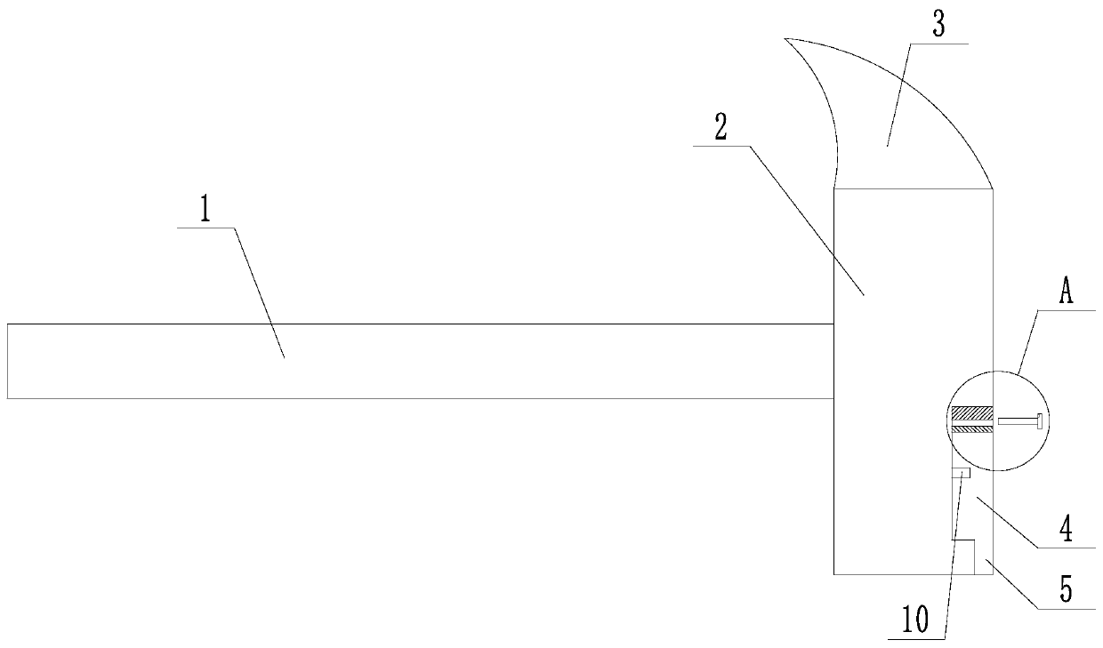
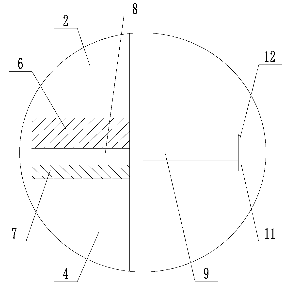
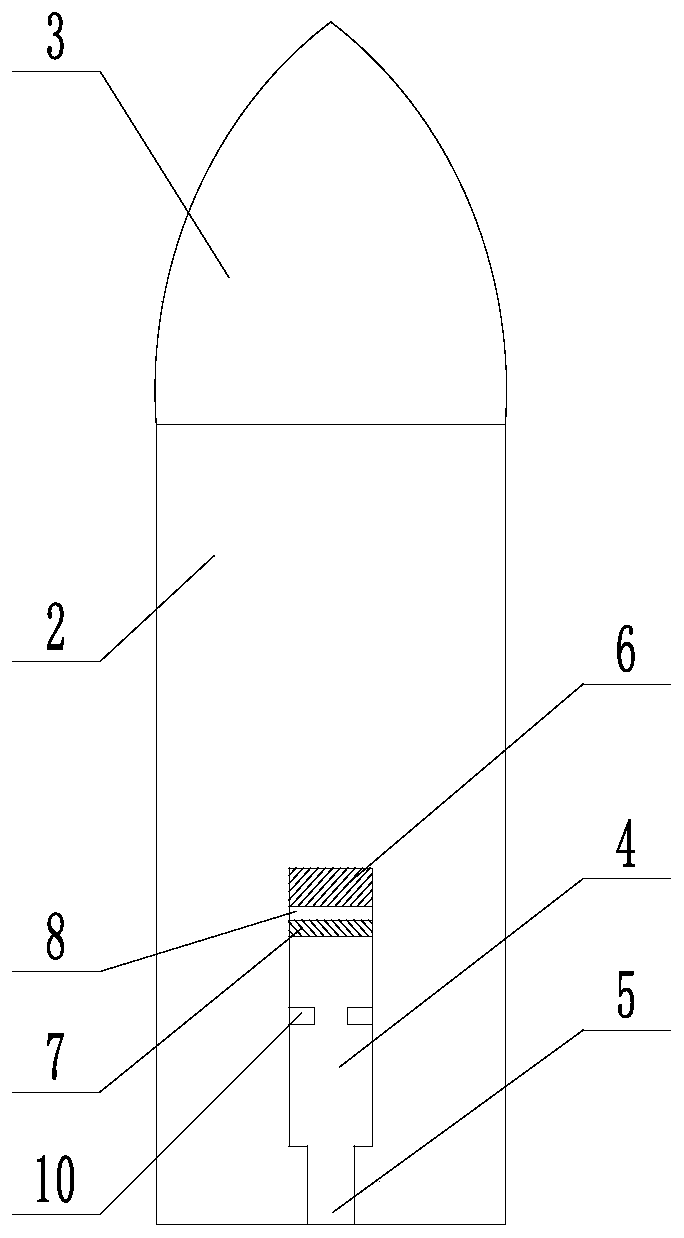
[0033] Such as Figure 1 to Figure 4 The shown stable and safe hammer assembly includes a rod body 1 and a hammer head that are connected to each other. The hammer head includes an integrally formed flat head 2 and a pointed cone 3, and the flat head 2 is square. The side surface of the flat head 2 in the direction away from the rod body 1 is the front side, the side surface of the flat head 2 in the direction away from the pointed cone portion 3 is the bottom surface, and the front side of the flat head 2 is provided with a first communicating with each other. The groove 4, the second groove 5, the second groove 5 is located between the first groove 4 and the bottom surface of the flat head 2, and the second groove 5 is open on the bottom surface of the flat head 2 The width and depth of the second groove 5 are smaller than those of the first groove 4; the side walls of the first groove 4 away from the direction of the second groove 5 fix the permanent magnet plate 6, the first...
Embodiment 2
[0035] Such as Figure 1 to Figure 5 A stable and safe hammer assembly shown in Embodiment 1 further includes an anti-knock assembly. The anti-knock assembly includes an elongated push plate 13, and one end of the push plate 13 along the long axis direction Two clamping plates 14 are fixedly connected. The two clamping plates 14 are symmetrical with respect to the long axis of the push plate 13. A clamping gap 15 is formed between the two clamping plates 14 and the clamping gap 15 is along the axis of the push plate 13. In the long axis direction, the width increases linearly from the end close to the push plate 13 to the end far away from the push plate 13. The clamping plate 14 is in the shape of a sector with a central angle of 85°, and one side of the sector is attached to the side of the push plate 13. The pushing plate 13 and the clamping plate 14 have the same thickness, and the upper and lower surfaces of the pushing plate 13 and the clamping plate 14 are flush. This e...
Embodiment 3
[0037] Such as Figure 1 to Figure 6 The shown stable and safe hammer assembly, on the basis of Embodiment 2, further includes a mounting block 16 fixed on the upper surface of the push plate 13. A first force transmission plate 17 is provided on the top of the mounting block 16. A force transmission plate 17 is hingedly connected to the end of the mounting block 16 away from the clamping plate 14. The bottom surface of the first force transmission plate 17 and the top surface of the mounting block 16 are connected with an elastic member 18; it also includes a fixed mounting block 16 facing away from the clamping plate 14 is located on the side of the L-shaped piece 19, the L-shaped piece 19 is bent upwards, the top of the L-shaped piece 19 is provided with a slider 20, and also includes a driving block 21, the bottom surface of the driving block 21 is arranged with the The sliding rail 22 that matches the sliding block 20, the sliding block 20 is located in the sliding rail 22...
PUM
 Abstract
Description
Claims
Application Information
 - R&D
- Intellectual Property
- Life Sciences
- Materials
- Tech Scout
- Unparalleled Data Quality
- Higher Quality Content
- 60% Fewer Hallucinations
Browse by: Latest US Patents, China's latest patents, Technical Efficacy Thesaurus, Application Domain, Technology Topic, Popular Technical Reports.
© 2025 PatSnap. All rights reserved.Legal|Privacy policy|Modern Slavery Act Transparency Statement|Sitemap|About US| Contact US: help@patsnap.com