Fast pin puller

A pin puller and fast technology, applied in hand-held tools, manufacturing tools, etc., can solve the problems of slipping, laborious cooperation between the pin puller and the positioning pin thread, etc., and achieve the effects of easy use, avoiding slipping, and improving pin pulling efficiency

Pending Publication Date: 2018-11-13
江门市蓬江区星硕方数控设备有限公司
View PDF1 Cites 1 Cited by
  • Summary
  • Abstract
  • Description
  • Claims
  • Application Information

AI Technical Summary

Problems solved by technology

But the surface of this pin puller is smooth surface, when rotating the pin puller to make it cooperate with the threaded hole on the locating pin, the phenomenon of slipping often occurs easily, so that it is laborious to make the pin puller and the locating pin screw thread fit.

Method used


Image

  • Fast pin puller
  • Fast pin puller
  • Fast pin puller

Examples


Embodiment Construction

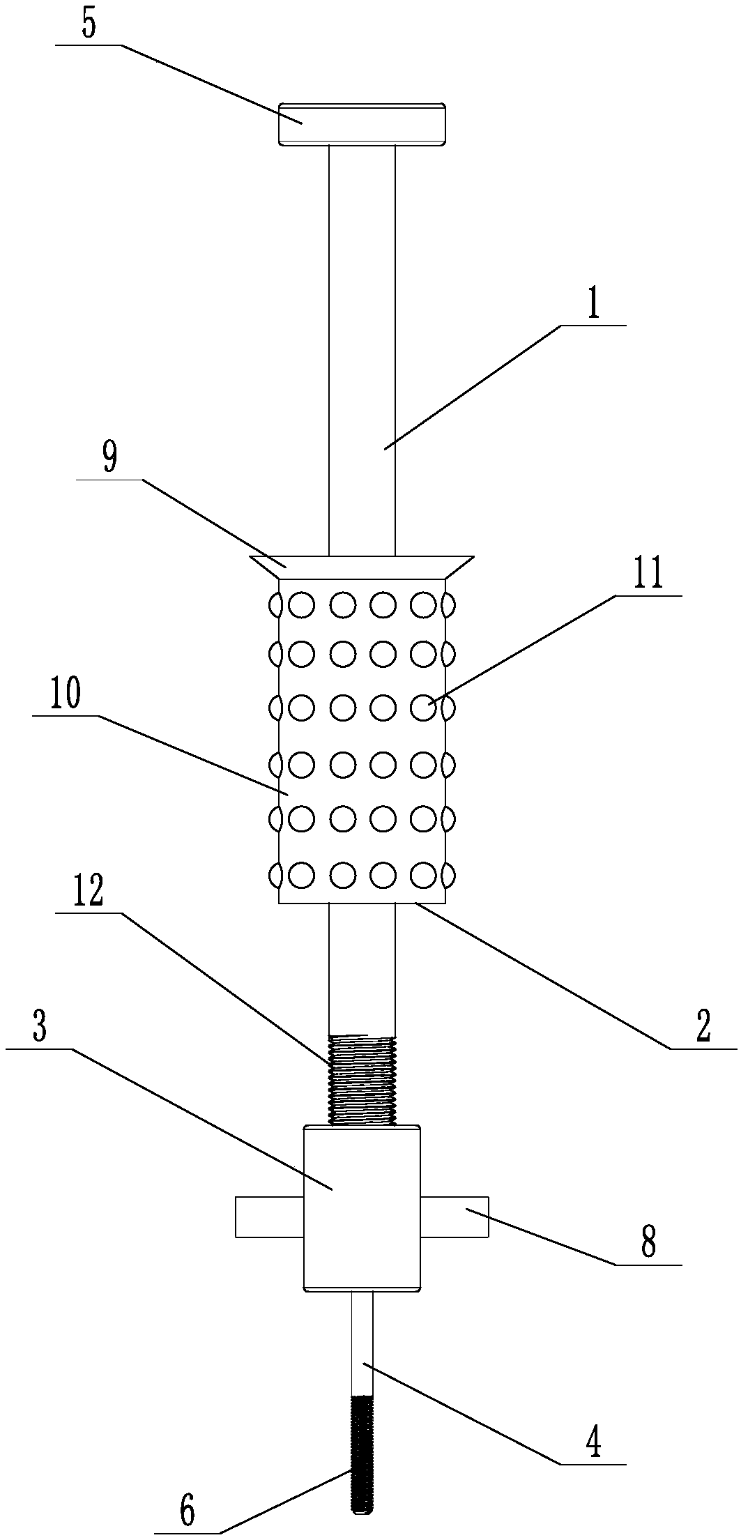
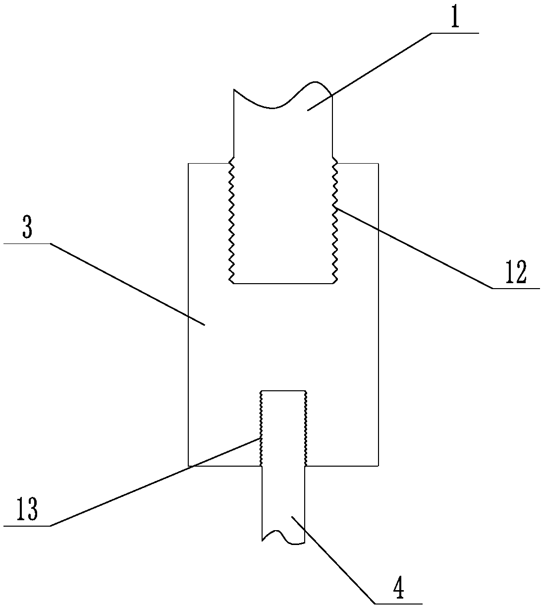
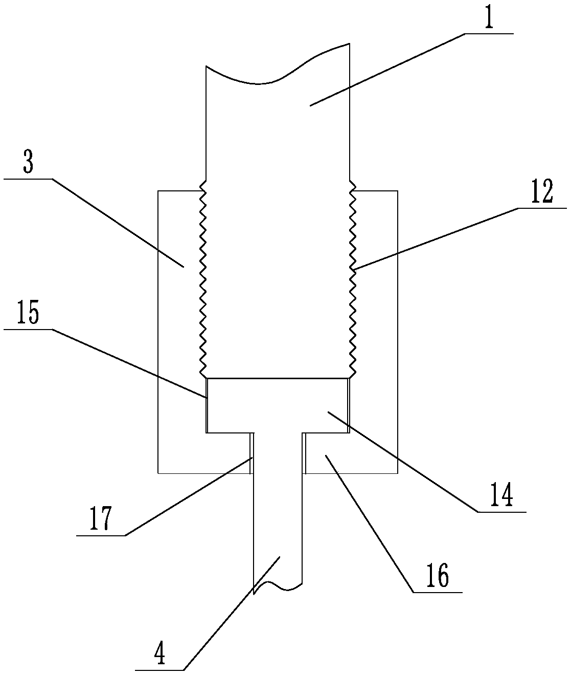
[0018] like Figure 1 to Figure 3 As shown, a quick pin puller includes a puller 1, a drive block 2, a connecting block 3 and a bolt 4. The puller 1 is arranged in a cylindrical shape, and the drive block 2 is installed in the middle of the puller 1 and can be opposite to the puller 1. Moving along its axial direction, the top of the pull rod 1 is provided with a positioning block 5 that abuts against the drive block 2 and limits the upward movement of the drive block 2, and the connecting block 3 is fixedly installed on the bottom end of the pull rod 1 through screw connection , the connecting block 3 abuts against the driving block 2 and limits the downward movement of the driving block 2. One end of the bolt 4 is provided with a first threaded connection part 6 that matches the threaded hole on the pin, and the other end is provided with a threaded connection part 6 for connecting with the The block 3 is fixedly connected to the mounting portion 7 , and the outer wall of th...


PUM


Abstract

The invention discloses a fast pin puller which comprises a pulling rod, a driving block, a connecting block and a bolt, wherein the pulling rod takes the shape of a cylinder; the driving block is mounted in the middle of the pulling rod and can move in the axis direction of the pulling rod relative to the pulling rod; a positioning block propped against the driving block and limiting the upward movement of the driving block is arranged at the top end of the pulling rod; the connecting block is fixedly mounted at the bottom end of the pulling rod through threaded connection; a first threaded connecting part matched with a threaded hole in a pin is arranged at one end of the bolt; a mounting part fixedly connected with the connecting block is arranged at the other end of the bolt; and a plurality of handles for driving the bolt to rotate are arranged on the outer wall of the connecting block in a protruding manner. The fast pin puller is convenient and labor-saving to use, facilitates cooperation of the pin puller and a locating pin and improves the pin pulling efficiency.

Description

technical field [0001] The invention relates to a mechanical equipment maintenance tool, in particular to a quick pin puller. Background technique [0002] The installation of parts with positional accuracy requirements in mechanical equipment usually uses cylindrical pins or tapered pins for precise positioning, so as to ensure the positional accuracy of parts installation or restore the original accuracy of the equipment after maintenance. Such as the power unit and base surface of the machine tool, the transmission mechanism, the reduction box and the motion guide rail, the frame and the oil pan of the diesel engine; the oil pump and the front end box, etc. The mounting holes of the positioning pins are hinged holes with high-precision roundness and surface roughness, and the mounting holes of the positioning pins and the connecting parts are all connected by interference fit. In order to facilitate the removal of cylindrical pins or tapered pins, one end of cylindrical ...

Claims


Application Information

Patent Timeline
IPC IPC(8): B25B27/02
CPCB25B27/023
Inventor 郭世明
Owner 江门市蓬江区星硕方数控设备有限公司
Why Eureka
Try Eureka