
Stable adsorption fixture

A jig and stable technology, used in manufacturing tools, workpiece clamping devices, etc., can solve problems such as inability to effectively fix the jig, large assembly errors, etc., to achieve easy assembly accuracy, avoid relative position movement, and high assembly accuracy. Effect

Pending Publication Date: 2018-11-13
CHENGDU JIANGYE OPTOELECTRONICS TECH
View PDF11 Cites 0 Cited by
  • Summary
  • Abstract
  • Description
  • Claims
  • Application Information

AI Technical Summary

Problems solved by technology

[0003] The purpose of the present invention is to provide a stable adsorption jig, aiming at the fact that the traditional assembly auxiliary jig cannot effectively fix the assembly parts in the jig during the moving process, which will easily cause large assembly errors and the traditional adsorption jig cannot be simultaneously adsorbed and fixed in different positions. The defects of the parts with high planes can realize the function of stably adsorbing and fixing the jig, avoiding the assembly error caused by the movement of the jig, and being able to absorb and fix two assembly parts at different height planes at the same time. It has the function of stably fixing the assembly parts and effectively avoiding the assembly caused by movement. Error, the effect of absorbing fixtures of different heights

Method used


Image

  • Stable adsorption fixture
  • Stable adsorption fixture
  • Stable adsorption fixture

Examples


Embodiment 1

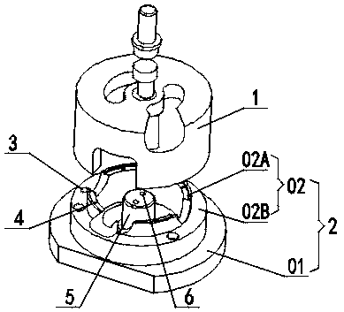
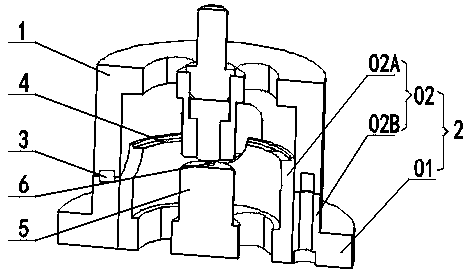
[0034] A stable adsorption fixture, such as figure 1 and figure 2As shown, it includes an upper jig 1 and a lower jig 2 that is movably engaged with the upper jig 1, and is characterized in that the lower jig 2 includes a bottom plate 01 and an annular outer wall 02 arranged on the bottom plate 01, The annular outer wall 02 includes an annular upper step 02A and an annular lower step 02B coaxially arranged in sequence from top to bottom, and the diameter of the upper step 02A is smaller than the diameter of the lower step 02B; the top of the upper step 02A There are several pendulum suction holes 4 penetrating through the bottom plate 01 on the surface; the top surface of the bottom plate 01 and the interior of the annular outer wall 02 are equipped with a lower stand 5, which is connected to the upper step 02A respectively. It is arranged coaxially with the lower step 02B; the top surface of the lower stand 5 is provided with several lower frame suction holes 6 penetrating ...

Embodiment 2

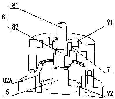
[0038] This embodiment is further optimized on the basis of the above-mentioned embodiment 1, such as image 3 and Figure 4 As shown, the upper jig 1 is provided with a hollow tubular movable snap-in cover that is movably engaged with the lower jig 2 , and the inner top of the movable snap-in cover corresponds to the lower stand 5 and is coaxially provided with a cylindrical upper The stand 7, the inside of the upper stand 7 is provided with an installation cavity 71 which penetrates up and down and is arranged coaxially with the lower stand 5, and the pressing device 8 is installed in the installation cavity 71. On the top surface of the lower step 02B and on the fastening surface of the upper jig 1 are provided with several corresponding adsorption holes along the circumferential direction, and magnets 3 are arranged in the adsorption holes; the upper jig 1 The upper correction hole 91 and the lower correction hole 92 are arranged correspondingly on the lower fixture 2, an...

Embodiment 3

[0046] This embodiment is further optimized on the basis of the above-mentioned embodiment 1, such as Figure 5 As shown, the bottom surface of the movable clamping cover of the upper fixture 1 and the step surface of the lower step 02B are also provided with corresponding positioning pin holes 03, and the positioning pin holes 03 are provided with positioning pins. The upper jig 1 is anti-rotationally locked with the lower jig 2 through positioning pins; one side of the bottom plate 01 is milled with a pressing plane 04; the outer wall of the upper jig 1 is also provided with a through groove penetrating the outer wall.

[0047] The positioning pin hole 03 corresponding to the position is also set on the step surface of the lower step 02B. After the upper jig 1 and the lower jig 2 are fastened, the positioning pin is inserted into the positioning pin hole 03 to avoid the upper jig 1 and the lower jig. There is relative rotation between the tools 2. On one side of the outer w...


PUM


Abstract

The invention discloses a stable adsorption fixture. The stable adsorption fixture comprises an upper jig and a lower jig movably bucked with the upper jig, wherein the lower jig comprises a baseplateand an annular outer wall arranged on the baseplate; the annular outer wall comprises an annular upper step and an annular lower step which are sequentially coaxially arranged from top to bottom; thediameter of the upper step is smaller than that of the lower step; a plurality of flap air intakes which penetrate the baseplate are formed in the top surface of the upper step; a lower standing table is mounted on the top surface of the baseplate, located inside the annular outer wall and are coaxial with the upper step and the lower step; and a plurality of lower framework air intakes which penetrate the baseplate are formed in the top surface of the lower standing table. The stable adsorption fixture can stably adsorb parts, guarantees the assembly precision, can be used in cooperation with a CCD industrial camera for alignment, is high in assembly accuracy and can easily guarantee the assembly precision.

Description

technical field [0001] The invention belongs to the technical field of assembly jigs, and in particular relates to a stable adsorption jig. Background technique [0002] The assembly of instrument components is a process that requires extremely high precision. When assembling instrument components, the components are usually placed in corresponding jigs for positioning, and then subsequent assembly work is performed. Especially in the precision assembly of instrument components, every time a component is assembled, a glue dispensing process is required. At this time, the jig and its components will move. The relative position of the relative position may be shifted with the shaking, vibration and other factors generated during the movement, resulting in a large assembly error, so that the accuracy of each component after assembly is not up to standard; at the same time, the general adsorption fixture can only be fixed by adsorption Components in the same plane cannot realiz...

Claims


Application Information

Patent Timeline
Patent Type & Authority Applications(China)
IPC IPC(8): B25B11/00
CPCB25B11/005
Inventor 李凯李鹏强岳永承
Owner CHENGDU JIANGYE OPTOELECTRONICS TECH
Learn More