
Combined synchronous type permanent magnet coupler

A permanent magnetic coupling, synchronous technology, applied in the direction of permanent magnetic clutch/brake, electric brake/clutch, electric components, etc., can solve problems such as installation difficulties, and achieve the effect of avoiding mutual attraction

Inactive Publication Date: 2018-11-06
江苏达锐斯永磁传动科技有限公司
View PDF0 Cites 1 Cited by
  • Summary
  • Abstract
  • Description
  • Claims
  • Application Information

AI Technical Summary

Problems solved by technology

[0003] The technical problem to be solved by the present invention overcomes the existing defects, provides a combined synchronous permanent magnet coupling, uses the combined structure to solve problems such as difficult installation, completely avoids the problem of mutual attraction between two rotors, and can effectively solve Problems in the Background Art

Method used


Image

  • Combined synchronous type permanent magnet coupler
  • Combined synchronous type permanent magnet coupler
  • Combined synchronous type permanent magnet coupler

Examples


Embodiment 1

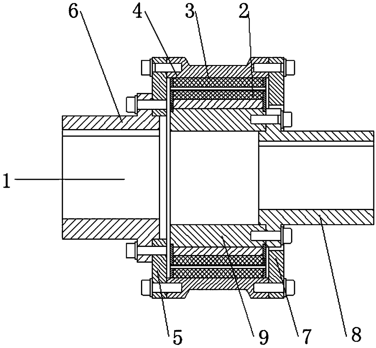
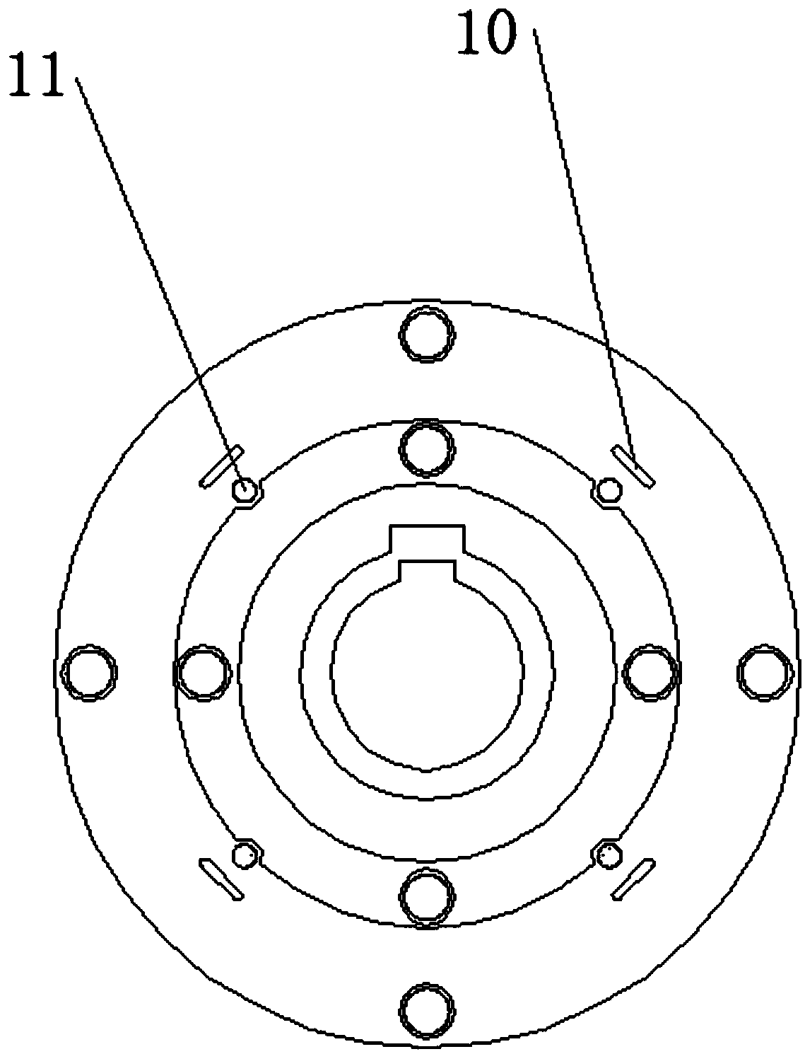
[0022] Embodiment 1: as Figure 1-2 As shown, the combined synchronous permanent magnet coupling includes a synchronous permanent magnet coupling body 1, and the synchronous permanent magnet coupling body 1 consists of a motor end bushing 6, a load end bushing 8 and a magnetic circuit The structure is composed of three parts, the three parts are connected together by connecting screws, and the magnetic circuit structure part is composed of connecting flange 1, connecting flange 2 7, driving rotor 4, driven rotor 9, driving rotor magnet 3, driven rotor magnet 2, and the active rotor 4, the active rotor magnet 3, the driven rotor magnet 2, and the driven rotor 9 are arranged sequentially from outside to inside, and an axial The positioning screw 11 and the radial positioning segment 10 are arranged outside the axial positioning screw 11 .

[0023] More specifically, the connecting flange one 5 is arranged on the left side of the connecting flange two 7, the motor end bushing 6 ...

Embodiment 2

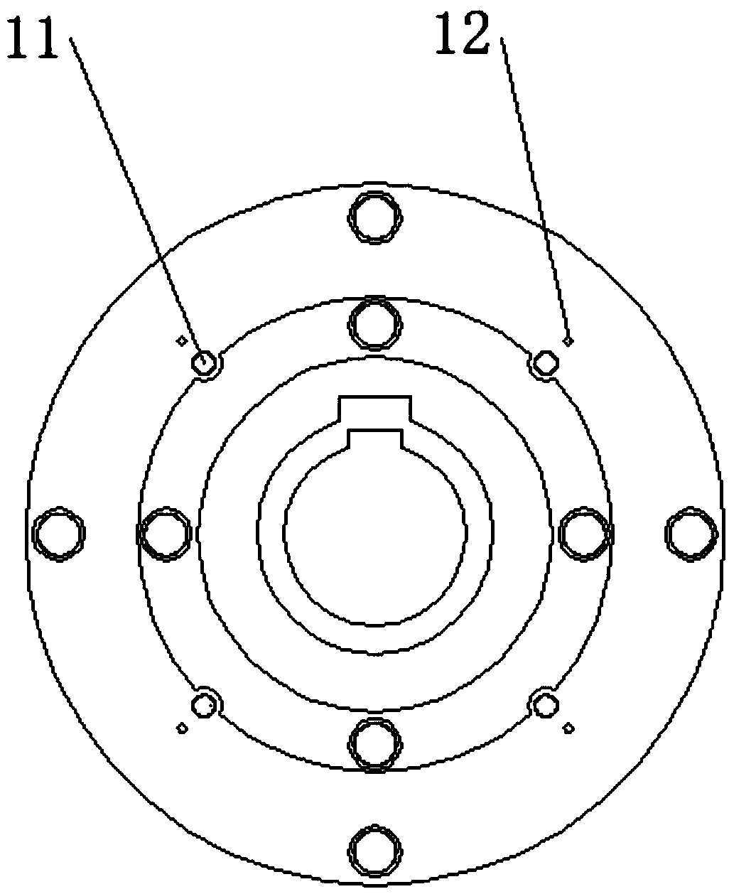
[0027] Embodiment 2: The radial positioning segment 10 in Embodiment 1 is replaced with a radial positioning pin 12 to achieve the same effect.

[0028] Completely solve the accidental suction of the rotor during transportation and installation, avoiding personal injury and equipment damage caused by suction; the combined structure makes the installation process easier, reduces the installation technical requirements for workers and masters, and reduces costs. Shorten the installation and maintenance cycle.

Embodiment 3

[0029] Embodiment 3: Remove the axial positioning jackscrew 11 in Embodiment 1, drill a hole in the outer circle of the active rotor, put a pin 13 in the hole, and the pin 13 is located between the magnetic block and the flange, and is used to control the two rotors The axial relative position between, basic principle is the same as embodiment 1.


PUM


Abstract

The invention relates to a combined synchronous type permanent magnet coupler which comprises a synchronous permanent magnet coupler body, wherein the synchronous permanent magnet coupler body consists of a motor end shaft sleeve, a load end shaft sleeve and a magnetic path structure; the three parts are connected together through connection screws; the magnetic path structure part is composed ofa connection flange I, a connection flange II, a driving rotor, a driven rotor, a driving rotor magnet and a driven rotor magnet; the driving rotor, the driving rotor magnet, the driven rotor magnet and the driven rotor are arranged in sequence from outside to inside; an axial locating jackscrew and a radial locating fan-shaped block are arranged between the driving rotor magnet and the driven rotor magnet; the radial locating fan-shaped block is arranged on the outer side of the axial locating jackscrew. The overall structure is optimized and improved deeply; the problems of installation difficulty and the like are solved by using the combined structure, and the problem of mutual attraction of two rotors is completely avoided.

Description

technical field [0001] The invention relates to a combined synchronous permanent magnet shaft coupling, which belongs to the field of shaft couplings. Background technique [0002] Coupling: A coupling is a device that connects two shafts or shafts and rotating parts, and rotates together without disengagement during the process of transmitting motion and power (torque), and does not change the direction of rotation and torque during transmission. The size of the permanent magnet coupling: The permanent magnet coupling is a new type of coupling that connects the prime mover and the working machine through the magnetic force of the permanent magnet. It consists of two rotors that are not mechanically connected to each other. The active rotor is connected to the motor shaft, and the driven rotor is connected to the load shaft. The rotor is equipped with rare earth permanent magnets. Using the interaction between the rare earth permanent magnets, the magnetic field can penetrat...

Claims


Application Information

Patent Timeline
Patent Type & Authority Applications(China)
IPC IPC(8): H02K49/10
CPCH02K49/102H02K49/106
Inventor 李新勇宋兴娇胡海军
Owner 江苏达锐斯永磁传动科技有限公司
Learn More