A light-emitting detection method of a light-emitting device based on computer vision

A technology of computer vision and optical equipment, applied in the field of image recognition, can solve problems such as hidden quality problems, inability to accurately analyze recorded data, and inability to accurately reflect light intervals in discharge intervals.

Active Publication Date: 2020-10-27
SHEN ZHEN COSBEAUTY CO LTD
View PDF3 Cites 0 Cited by
  • Summary
  • Abstract
  • Description
  • Claims
  • Application Information

AI Technical Summary

Problems solved by technology

The oscilloscope detects and records the interval between two adjacent discharges. The discharge interval of this method cannot accurately reflect the light interval, and the number of records is too small to make statistics. However, the manual stopwatch is used to record the interval between two adjacent discharges. This method is not accurate enough for timing , the recorded data cannot be analyzed accurately
[0004] In short, the existing light-emitting device detection method has inaccurate statistical results, insufficient statistics of recording times, and large errors, which cannot be applied to mass production testing of products. The quality evaluation work has brought great inconvenience, and the test results with large errors have brought quality hidden dangers to the tested products.

Method used


Image

  • A light-emitting detection method of a light-emitting device based on computer vision
  • A light-emitting detection method of a light-emitting device based on computer vision
  • A light-emitting detection method of a light-emitting device based on computer vision

Examples


Embodiment 1

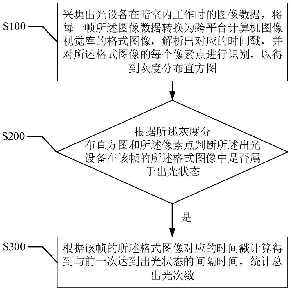
[0061] refer to figure 2 , the first embodiment of the present invention provides a computer vision-based light output detection method for a light output device, including:

[0062] Step S100, collect the image data of the light-emitting device when it is working in the darkroom, convert the image data of each frame into a format image of a cross-platform computer image vision library, parse out the corresponding time stamp, and analyze each frame of the image in the format Pixels are identified to obtain a gray distribution histogram;

[0063] As mentioned above, the light-emitting device is a flash device that can emit light automatically or manually in real time and regularly, for example, photon hair removal instrument, photon beauty device, photon therapy device, photon sintering device and so on.

[0064] As mentioned above, in this implementation, the detection of the light-emitting device can be a photon hair removal instrument system assembled by multiple devices, ...

Embodiment 2

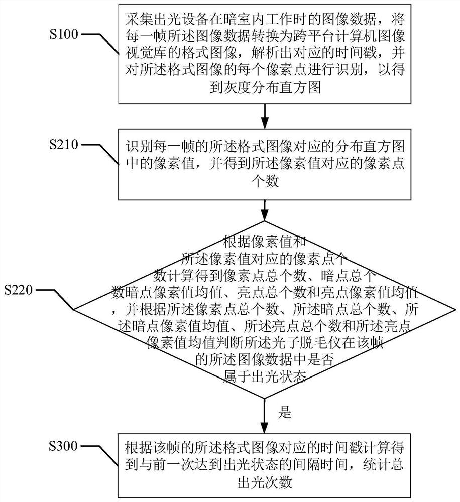
[0083] refer to image 3 , the second embodiment of the present invention provides a computer vision-based light-emitting device light detection method, based on the above figure 2 In the first embodiment shown, the step S200 of "judging whether the light emitting device belongs to the light emitting state in the format image of the frame according to the gray distribution histogram and the pixel points" includes:

[0084] Step S210, identifying the pixel value in the distribution histogram corresponding to the format image of each frame, and obtaining the number of pixel points corresponding to the pixel value;

[0085] Above, it needs to be explained that a pixel is composed of small squares of the image, the so-called pixels. These small squares have a clear position and an assigned color value, and the color of these small squares and position determine how the image will appear. A pixel can be regarded as an indivisible unit or element in the entire image. Indivisible ...

Embodiment 3

[0092] refer to Figure 4 , the third embodiment of the present invention provides a computer vision-based light-emitting device light detection method, based on the above image 3 In the second embodiment shown, the step S220 "according to the pixel value and the number of pixels corresponding to the pixel value is calculated to obtain the total number of pixels, the total number of dark spots, the average value of the pixel value of dark spots, and the total number of bright spots number and the average value of bright pixel values, and judge the light output according to the total number of pixels, the total number of dark spots, the average value of dark pixel values, the total number of bright spots, and the average value of bright pixel values Whether the device is in the light emitting state in the image data of the frame" includes:

[0093] Step S221, if the pixel value corresponding to the pixel point is less than the preset dark point value, then determine that the ...


PUM


Abstract

The invention provides a light extraction detection method of light extraction equipment, based on computer vision. The light extraction detection method includes the steps: collecting image data, converting the image data into a format image, analyzing a corresponding time stamp, and identifying each pixel of the format image to obtain a gray scale distribution histogram; according to the gray scale distribution histogram and the pixel points, determining whether the light extraction equipment belongs to the light extracting state in the format image of the frame; and if the light extractionequipment belongs to the light extracting state in the format image of the frame, according to the time stamp corresponding to the format image of the frame, calculating to obtain the interval from the previous light extracting state, and counting the total number of times of light extracting. The light extraction detection method of light extraction equipment, based on computer vision improves the precision of the detection result, reduces the detection error, brings great convenience to the quality evaluation work of the light extraction equipment in the process of product development, production, quality control, etc., guarantees reliability of the quality of each detection product, and puts an end to a hidden trouble of quality.

Description

technical field [0001] The present invention relates to the technical field of image recognition, and more specifically, to a computer vision-based light output detection method, device and user terminal of a light output device. Background technique [0002] The light-emitting device is a flash device that can emit light automatically or manually in real time and at regular intervals, for example, photon hair removal equipment, photon beauty equipment, photon therapy equipment, photon sintering equipment, etc. Among them, photon hair removal instrument, its core technology is photon hair removal, also known as IPL photon hair removal, in which IPL (Intense Pulsed Light) is called intense pulsed light, also known as colored light, composite light, strong light, is an effective Broad-spectrum visible light with a special wavelength has a softer photothermal effect. [0003] In the process of product development and production of light-emitting devices, it is necessary to det...

Claims


Application Information

Patent Timeline
Patent Type & Authority Patents(China)
IPC IPC(8): G06T7/00
CPCG06T7/001G06T2207/10004G06T2207/30164
Inventor 冼土濂裴碧波赵立群陶淳方自然黄万富
Owner SHEN ZHEN COSBEAUTY CO LTD
Why Eureka
Try Eureka