
Capacitive pressure detection device

A detection device and capacitive technology, which is applied to the input/output process of electrical digital data processing, instruments, and data processing, etc., can solve the problems of forming pressure detection capacitors, difficult to control the thickness of air gaps, and unable to realize pressure detection, etc. The effect of securing the capacitance change rate, securing the gap thickness, and improving the sensitivity

Inactive Publication Date: 2018-11-06
SHENZHEN FOCALTECH SYST
View PDF7 Cites 0 Cited by
  • Summary
  • Abstract
  • Description
  • Claims
  • Application Information

AI Technical Summary

Problems solved by technology

[0003] 1. There needs to be an air gap of sufficient thickness between the display module and the backlight module to ensure that the pressure detection capacitance change that is sufficiently different from the interference signal can be generated when the pressing action occurs, but the air cannot resist the change between the structures and make the air gap The thickness is not easy to control;
[0004] 2. Not all displays are equipped with backlight modules with iron frames;
[0005] When the display module adopts a Thin Film Transistor Liquid CrystalDisplay display module, some applications use a backlight module with a non-metal frame, so that the backlight module with a non-metal frame cannot be used as a reference plane and a pressure detection electrode. Pressure detection capacitance is formed, so pressure detection cannot be realized; thin film transistor liquid crystal display Thin Film Transistor Liquid Crystal Display is referred to as TFT-LCD;

Method used


Image

  • Capacitive pressure detection device
  • Capacitive pressure detection device
  • Capacitive pressure detection device

Examples


Embodiment Construction

[0030] Further details will be given below in conjunction with various embodiments shown in the accompanying drawings.

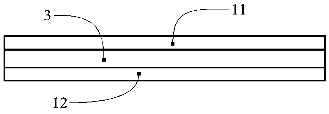
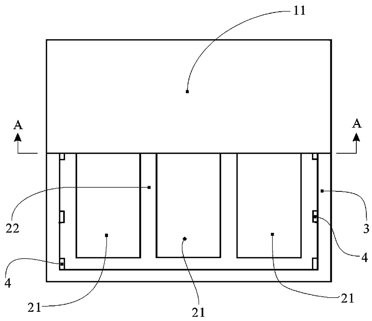
[0031] The invention provides a capacitive pressure detection device for detecting the pressing force applied on the display screen. The pressing force applied on the display screen is different from the touch input to the screen. The pressing force is to exert pressure on the display screen, while the touch input does not need to apply pressure, but only needs to have contact with the display screen. The display screen includes a display module capable of being deformed by pressing on the display screen. Such as Figure 1 to Figure 7As shown, the capacitive pressure detection device includes a first substrate 11 and a second substrate 12 that can be deformed under pressure, at least one first electrode 21 disposed on the front surface of the first substrate 11, disposed on the second substrate At least one second electrode 22 on the front surface of 12, a...


PUM


Abstract

The invention discloses a capacitive pressure detection device. The device is used for detecting pressing force applied to a display screen, and includes a first substrate and a second substrate respectively provided with electrodes and a data processing module. Front surfaces of the first substrate and the second substrate are relatively bonded together to enable a gap to be formed between the respectively disposed electrodes. The gap is communicated with air outside the first substrate and the second substrate. At least one substrate in the first substrate and the second substrate is used asa pressure bearing surface. The pressure bearing surface can be attached below a display module of the display screen. The device does not need to rely on components in the display screen to form pressure detection capacitance, and can be suitable for use in most current display screens. The device provides physical support for forming the gap of the pressure detection capacitance, and ensures that gap thickness is controllable. The device ensures a capacitance change rate of the pressure detection capacitance through a substrate material and a foam cotton medium, and improves sensitivity ofpressure detection.

Description

technical field [0001] The invention relates to a device for collecting and converting force into electrical signals, in particular to a pressure detection device which uses capacitance as a conversion medium and processes electrical signals reflecting pressure into pressure data. Background technique [0002] In the prior art, a display screen capable of detecting pressing force applied thereon based on the capacitance principle includes a display module for image display, pressure detection electrodes, and a backlight module with an iron frame. One implementation is that the pressure detection electrode is bonded to the display module, an air gap is formed between the pressure detection electrode and the backlight module, and the pressure detection capacitor is formed between the pressure detection electrode and the backlight module with the iron frame of the backlight module as the reference plane. . When a pressing force is applied on the display screen, the pressure de...

Claims


Application Information

Patent Timeline
Patent Type & Authority Applications(China)
IPC IPC(8): G06F3/041G06F3/044
CPCG06F3/0412G06F3/0414G06F3/044
Inventor 贡振邦黄海舰骆志强肖钡
Owner SHENZHEN FOCALTECH SYST
Learn More