optical imaging system
An optical imaging system and imaging surface technology, applied in optics, optical components, instruments, etc., can solve the problems of high positioning accuracy and inability to correct f-theta distortion strictly, and achieve the effect of high positioning accuracy and high imaging quality
- Summary
- Abstract
- Description
- Claims
- Application Information
AI Technical Summary
Problems solved by technology
Method used
Image

Examples
Embodiment 1
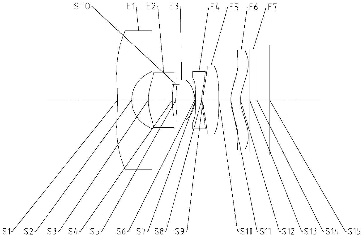
[0069] Refer to the following Figure 1 to Figure 2C An optical imaging system according to Embodiment 1 of the present application is described. figure 1 A schematic structural diagram of an optical imaging system according to Embodiment 1 of the present application is shown.
[0070] Such as figure 1 As shown, the optical imaging system according to the exemplary embodiment of the present application includes sequentially along the optical axis from the object side to the image side: a first lens E1, a second lens E2, a diaphragm STO, a third lens E3, and a fourth lens E4 , the fifth lens E5, the sixth lens E6, the filter E7 and the imaging surface S15.
[0071]The first lens E1 has negative refractive power, its object side S1 is concave, the image side S2 is concave, and the object side S1 has an inflection point; the second lens E2 has positive refractive power, its object side S3 is convex, and the image side S3 is convex. S4 is a concave surface; the third lens E3 ha...
Embodiment 2
[0097] Refer to the following Figure 3 to Figure 4C An optical imaging system according to Embodiment 2 of the present application is described. In this embodiment and the following embodiments, for the sake of brevity, descriptions similar to those in Embodiment 1 will be omitted. image 3 A schematic structural diagram of an optical imaging system according to Embodiment 2 of the present application is shown.
[0098] Such as image 3 As shown, the optical imaging system according to the exemplary embodiment of the present application includes sequentially along the optical axis from the object side to the image side: a first lens E1, a second lens E2, a diaphragm STO, a third lens E3, and a fourth lens E4 , the fifth lens E5, the sixth lens E6, the filter E7 and the imaging surface S15.
[0099] The first lens E1 has negative refractive power, its object side S1 is concave, the image side S2 is concave, and the object side S1 has an inflection point; the second lens E2 ...
Embodiment 3
[0112] Refer to the following Figure 5 to Figure 6C An optical imaging system according to Embodiment 3 of the present application is described. Figure 5 A schematic structural diagram of an optical imaging system according to Embodiment 3 of the present application is shown.
[0113] Such as Figure 5 As shown, the optical imaging system according to the exemplary embodiment of the present application includes sequentially along the optical axis from the object side to the image side: a first lens E1, a second lens E2, a diaphragm STO, a third lens E3, and a fourth lens E4 , the fifth lens E5, the sixth lens E6, the filter E7 and the imaging surface S15.
[0114] The first lens E1 has negative refractive power, its object side S1 is concave, the image side S2 is concave, and the object side S1 has an inflection point; the second lens E2 has positive refractive power, its object side S3 is convex, and the image side S3 is convex. S4 is a concave surface; the third lens E3...
PUM
 Abstract
Description
Claims
Application Information
 - R&D
- Intellectual Property
- Life Sciences
- Materials
- Tech Scout
- Unparalleled Data Quality
- Higher Quality Content
- 60% Fewer Hallucinations
Browse by: Latest US Patents, China's latest patents, Technical Efficacy Thesaurus, Application Domain, Technology Topic, Popular Technical Reports.
© 2025 PatSnap. All rights reserved.Legal|Privacy policy|Modern Slavery Act Transparency Statement|Sitemap|About US| Contact US: help@patsnap.com