
A Magnetic Target Location Method Based on Magnetic Sensor Array Coordinate System

A magnetic sensor and magnetic target technology, applied in the direction of point coordinate measurement, electric/magnetic position measurement, instruments, etc., can solve the problems of slow calculation speed, sensitive initial value, non-rapid convergence in special areas, etc., to speed up calculation speed and reduce The number of iterations, the effect of overcoming the non-fast convergence problem

Active Publication Date: 2019-08-09
HUAZHONG UNIV OF SCI & TECH
View PDF8 Cites 1 Cited by
  • Summary
  • Abstract
  • Description
  • Claims
  • Application Information

AI Technical Summary

Problems solved by technology

[0004] Aiming at the above defects or improvement needs of the prior art, the present invention provides a magnetic target positioning method based on the magnetic sensor array coordinate system, thereby solving the problems of slow calculation speed, initial value sensitivity, and abnormality in special areas in the existing magnetic target positioning method. Rapid Convergence Technical Issues

Method used


Image

  • A Magnetic Target Location Method Based on Magnetic Sensor Array Coordinate System
  • A Magnetic Target Location Method Based on Magnetic Sensor Array Coordinate System
  • A Magnetic Target Location Method Based on Magnetic Sensor Array Coordinate System

Examples


Embodiment 1

[0055] A magnetic target positioning method based on a magnetic sensor array coordinate system, comprising:

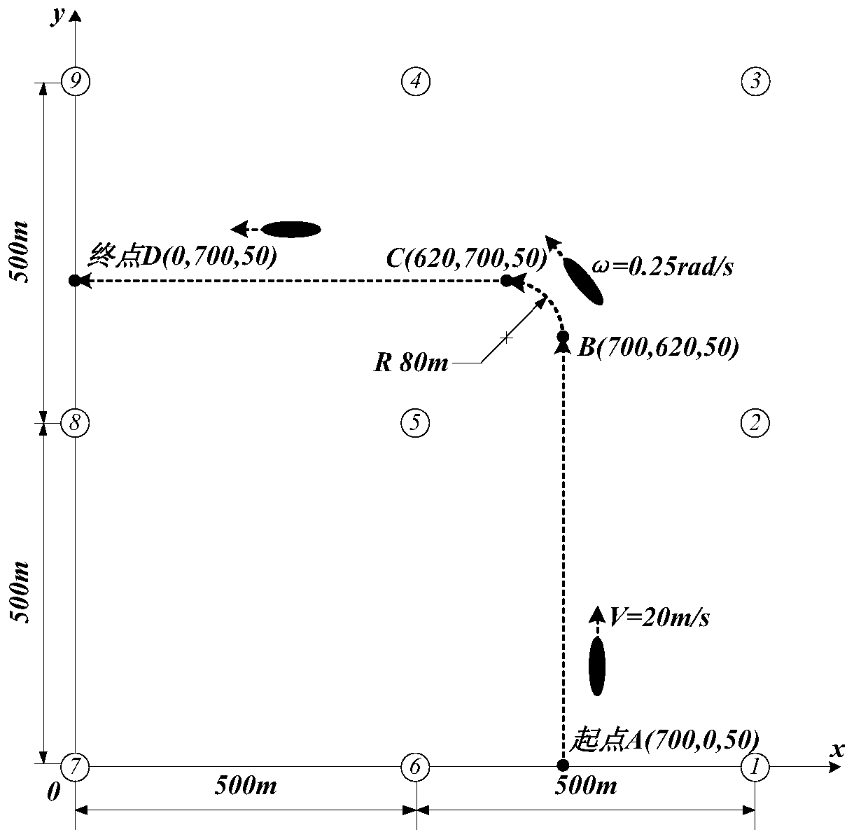
[0056] (1) Arrange 9 three-axis magnetic sensors on the same plane in a square array to ensure that the three-axis X, Y, and Z directions of each magnetic sensor are consistent, and number each node in turn, taking the position of node 7 As the coordinate origin, set up a space Cartesian coordinate system with the directions of the three axes X, Y, and Z of the magnetic sensor, and write down the position coordinates of each magnetic sensor. The position coordinates of each magnetic sensor in Embodiment 1 of the present invention are shown in Table 1.

[0057] Table 1 Position coordinates of the magnetic sensor

[0058] Sensor number Sensor position coordinates (unit: m) 1 (1000,0,0) 2 (1000,500,0) 3 (1000,1000,0) 4 (500,1000,0) 5 (500,500,0) 6 (500,0,0) 7 (0,0,0) 8 (0,500,0) 9 (0,1000,0)

[0059] (2) After ...


PUM


Abstract

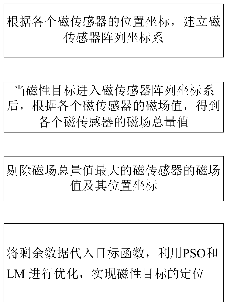
The present invention discloses a magnetic target location method based on a magnetic sensor array coordinate system. The method comprises the steps of: establishing a magnetic sensor array coordinatesystem according to the position coordinates of each magnetic sensor, and after a magnetic target enters the magnetic sensor array coordinate system, collecting the magnetic field value of each magnetic sensor; according to the magnetic field value of each magnetic sensor, obtaining the magnetic field total amount value of each magnetic sensor, rejecting the magnetic field value and the positioncoordinates of the magnetic sensor with the maximum magnetic field total amount value, and obtaining remaining data; and employing the magnetic field value of each magnetic sensor to establish a target function, substituting the remaining data into the target function, employing a particle swarm optimization and an LM to perform optimization of the target function, and obtaining a location resultof a magnetic target. The method is rapid and effective, and can meet the timeliness and accuracy requirements of magnetic target location.

Description

technical field [0001] The invention belongs to the field of magnetic target positioning, and more particularly relates to a magnetic target positioning method based on a magnetic sensor array coordinate system. Background technique [0002] Real-time monitoring of magnetic targets needs to meet two requirements: real-time and accuracy. The essence of the current positioning method is to use the magnetic dipole model to derive a nonlinear equation system, and then solve the nonlinear equation system. Classical iterative methods are often used to solve this nonlinear equation system, such as Gauss-Newton method, gradient descent method, LM (Levenberg-Marquardt) algorithm, etc. These methods are fast in calculation but need to provide reasonable initial values ​​artificially. If the initial value is selected Unreasonable, the calculation result is very unstable. While the global intelligent optimization algorithm can overcome the initial value sensitivity problem, but the ca...

Claims


Application Information

Patent Timeline
Patent Type & Authority Patents(China)
IPC IPC(8): G01B7/00G01B7/004
CPCG01B7/003G01B7/004
Inventor 杨晓非孙文王鲜然葛旭
Owner HUAZHONG UNIV OF SCI & TECH
Learn More