
Elevator shaft operation platform

A technology for operating platforms and elevator shafts, which is applied in the direction of housing structure support, housing structure support, and scaffolding supported by housing structures, etc. problems, to improve the stability and safety of use, improve the construction environment, and achieve the effect of reasonable structural design.

Active Publication Date: 2018-11-06
CHINA METALLURGICAL CONSTR ENG GRP
View PDF8 Cites 0 Cited by
  • Summary
  • Abstract
  • Description
  • Claims
  • Application Information

AI Technical Summary

Problems solved by technology

[0003] In order to facilitate construction on the operation platform, it is necessary to ensure that the upper surface of the operation platform is level. In order to ensure sufficient structural strength, the current custom-made operation platform usually adopts an integrated structure, which cannot be adapted according to the plane size of the elevator shaft. adjust
Within the error range, no matter whether the plane size of the elevator shaft is too large or too small, the inclination angle of the diagonal brace will be changed, which will affect the inclination angle of the upper surface of the operating platform and affect the stable construction of the construction personnel
Moreover, for elevator shafts with too small planar dimensions, the gap between the operating platform and the elevator shaft will be too small. When the operating platform is lifted, the operating platform will easily scratch the inner wall of the elevator shaft.

Method used


Image

  • Elevator shaft operation platform
  • Elevator shaft operation platform

Examples


Embodiment Construction

[0027] The present invention will be described in further detail below in conjunction with embodiment.

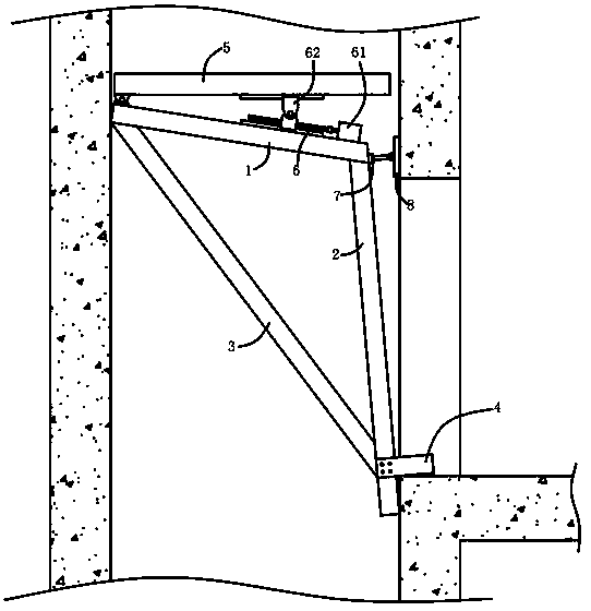
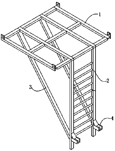
[0028] During specific implementation: if figure 1 As shown, an elevator shaft operating platform is supplemented with the structure of the existing elevator shaft operating platform for ease of understanding, such as figure 2 As shown, it includes a top frame 1 arranged horizontally and in a rectangular shape as a whole, a support frame 2 vertically arranged is fixedly installed on one side of the top frame 1, and a diagonal brace is fixedly installed between the top frame 1 and the support frame 2 3, the lower end of the brace 3 is connected to the lower end of the support frame 2, and the upper end is connected to the side of the top frame 1 away from the support frame 2; the position of the support frame 2 near the bottom has a The corbel 4 vertically arranged in the direction away from the diagonal brace 3, the top frame 1 is also provided with lifting lugs for lifti...


PUM

PropertyMeasurementUnit
Angleaaaaaaaaaa

Abstract

The invention discloses an elevator shaft operation platform, which comprises a top frame, wherein the top frame is transverse arrangement; the whole of the top frame is in a rectangular shape; a support frame in vertical arrangement is fixedly arranged at one side of the top frame; an inclined support element is fixedly arranged between the top frame and the support frame; a bracket in vertical arrangement in a direction backing to the inclined support element is arranged in a position, near the bottom, of the support frame; a hoisting lug used for hoisting is arranged on the top frame; an included angle between the top frame and the support frame is greater than 90 degree; when the bracket and the upper end of the inclined support element are supported in the elevator shaft, the height of one side, near the support frame, of the top frame is always lower than the height of the other side; a construction platform is hinged to a position above one side, backing to the support frame, ofthe top frame; the whole of the construction platform is in a rectangular shape; and a height regulating mechanism is arranged between the top frame and a position, far away from a hinging shaft, ofthe construction platform. The elevator shaft operation platform has the advantages that the structural design is reasonable; the construction platform can be enabled to be in a horizontal state; theconstruction is convenient; and the construction environment is favorably improved, and the like.

Description

technical field [0001] The invention relates to the technical field of building construction, in particular to an elevator shaft operating platform. Background technique [0002] In the modern construction industry, there are more and more high-rise buildings, and elevators have become an indispensable part of high-rise buildings. The elevator shaft is a reinforced concrete shear wall structure, the foundation plane size is small, the height is high, the shear wall is densely reinforced, and it is an independent structure. The elevator shaft is a passage that runs through the top and bottom. The elevator shaft is a high-altitude operation during the construction process. The safe operation and protection of the elevator shaft construction is a link that cannot be ignored, and there are certain risk factors. During the construction of the elevator shaft, it is necessary to set up an operating platform in the elevator shaft. The operating platform set up in the shaft is often...

Claims


Application Information

Patent Timeline
IPC IPC(8): E04G3/24
CPCE04G3/246
Inventor 岳广辉魏庆滨
Owner CHINA METALLURGICAL CONSTR ENG GRP
Learn More