Reed end shaping system and shaping method

A technology of end shaping and reed, which is applied in the field of leaf spring processing devices, can solve the problems of reed raw materials, waste cannot be recycled, and tool wear is fast, so as to save the cost of tools, reduce equipment wear, and save tool replacement. the effect of time

Active Publication Date: 2020-04-28
SHANDONG AUTOMOBILE SPRING FACTORY ZIBO CO LTD
View PDF10 Cites 0 Cited by
  • Summary
  • Abstract
  • Description
  • Claims
  • Application Information

AI Technical Summary

Problems solved by technology

[0005] The above-mentioned shaping process requires a lot of reed raw materials. During the second step, because the whole process is thermal processing, the cutters of the cutting head and angle cutting composite mold are worn quickly and need to be replaced frequently, resulting in increased costs; and the cut off waste cannot be Recycling, resulting in waste of raw materials, relatively high production costs

Method used


Image

  • Reed end shaping system and shaping method
  • Reed end shaping system and shaping method
  • Reed end shaping system and shaping method

Examples


Embodiment 1

[0044] The reed end shaping system includes a reed extruding die and a reed racket die, wherein:

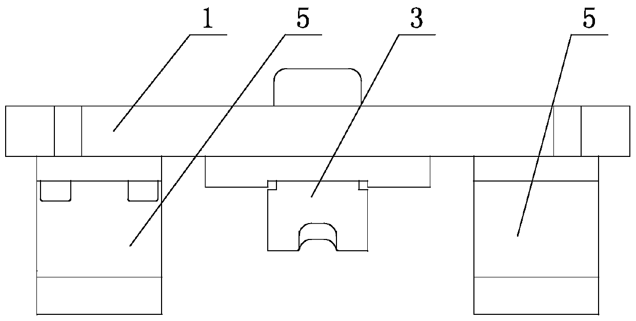
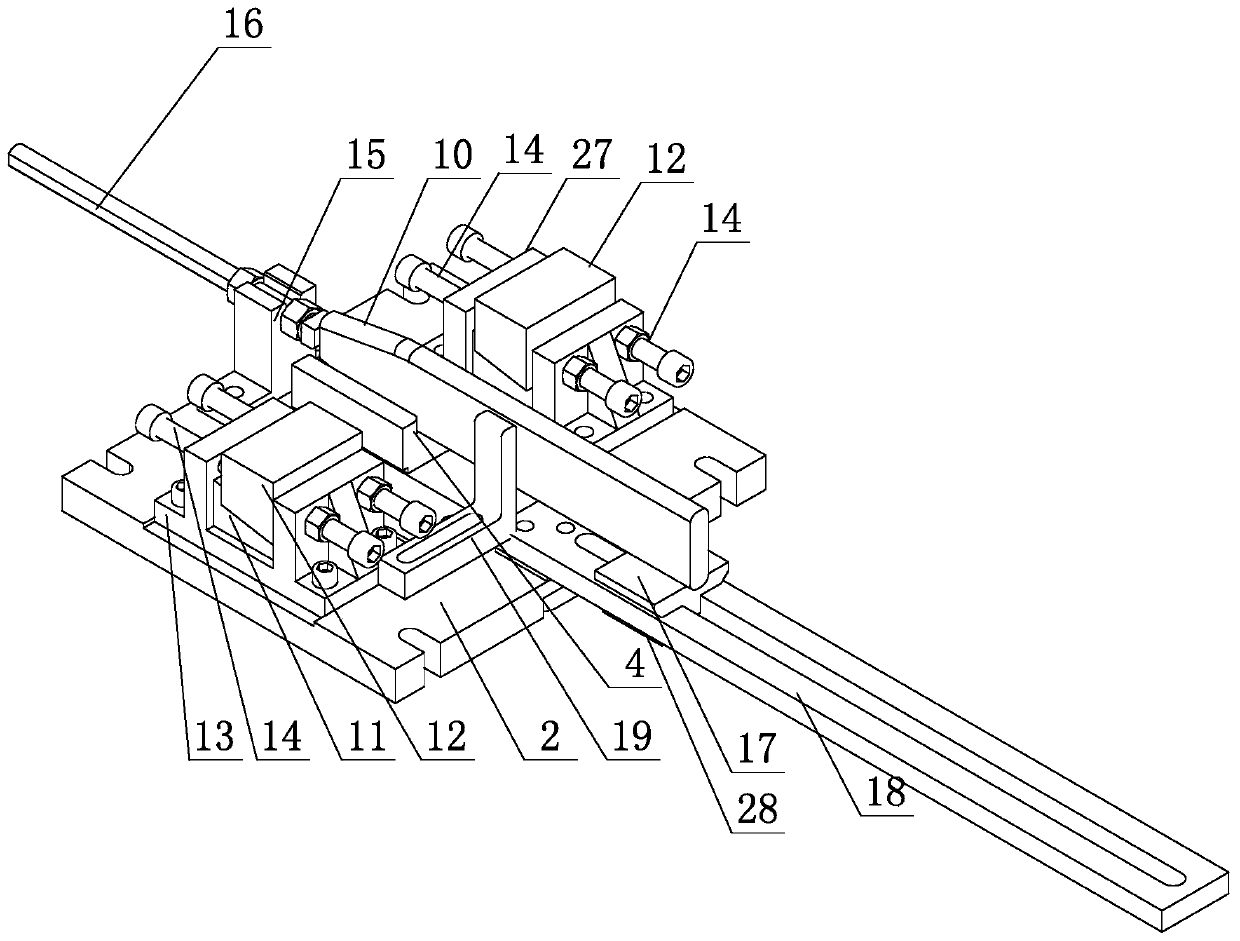
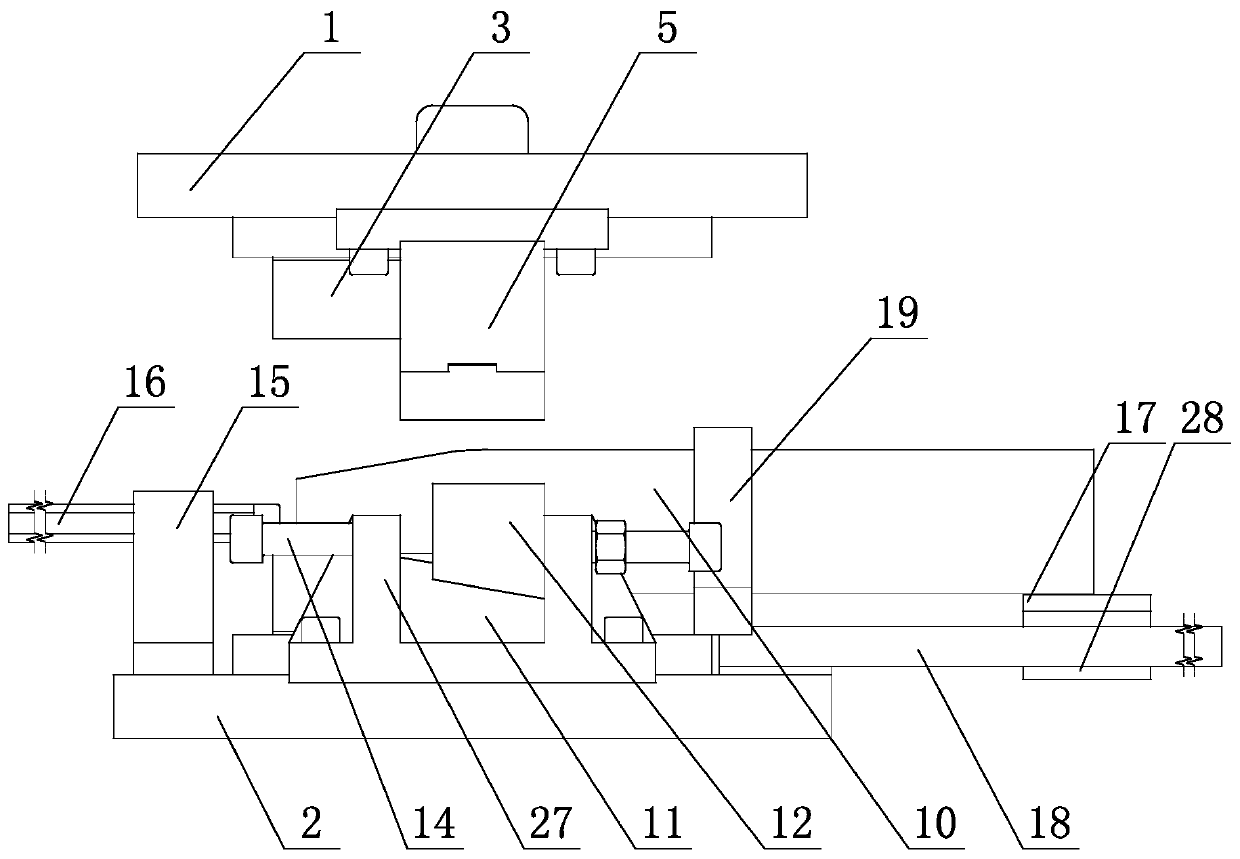
[0045] like Figure 1-3 As shown, the reed extrusion head mold includes an upper extrusion head template 1 and an extrusion head lower template 2, and an upper extrusion head seat 3 and a lower extrusion head seat 4 are relatively arranged on the extrusion head upper template 1 and the extrusion head lower template 2. The extrusion head briquetting blocks 5 are fixed on both sides of the extrusion head seat 3, the extrusion head height adjustment parts are set on both sides of the lower extrusion head seat 4 corresponding to the extrusion head block 5, and the extrusion head is set on the front end of the lower extrusion head seat 4 corresponding to the extrusion head lower template 2 As for the positioning part, the extrusion head supporting piece is arranged on the rear end of the extrusion head lower template 2 corresponding to the lower extrusion head seat 4;

[0046] like ...

Embodiment 2

[0053] This embodiment provides a method for reed end shaping on the basis of Embodiment 1, comprising the following steps:

[0054] The first step is to cut off the material, and cut the spring flat steel into reed 10 according to the required length;

[0055] The second step, drilling, drills the center hole for the reed 10 by the drilling mold;

[0056] The third step is heating, the reed 10 is heated at the end by intermediate frequency, and the heating length is determined according to the end processing length of the reed 10;

[0057] The fourth step is to squeeze the head, and squeeze the reed 10 through the reed head extrusion die;

[0058] The fifth step is the racket head, and the reed 10 is racketed through the reed racket head mold.

[0059] The first step to the third step above are the same as the existing process, and the specific process will not be repeated. The specific process of the fourth step is:

[0060] Place the heated reed 10 on the lower extrusion...


PUM


Abstract

The invention relates to a spring leaf end shaping device, in particular to a spring leaf end shaping system comprising a spring leaf end squeezing die and a spring leaf end beating die. The spring leaf end squeezing die comprises an end squeezing upper die plate and an end squeezing lower die plate, and the end squeezing upper die plate and the end squeezing lower die plate are oppositely provided with an upper end squeezing seat and a lower end squeezing seat. The spring leaf end beating die comprises an end beating upper die plate and an end beating lower die plate. The end beating upper die plate and the end beating lower die plate are oppositely provided with an end beating block and an end beating seat. The invention further relates to a spring leaf end shaping method. The spring leaf end shaping method comprises the steps of firstly, breaking a material, wherein spring flat steel is cut into spring leaves according to the needed length; secondly, drilling a hole, wherein a center hole is drilled for each spring leaf through a hole drilling die; thirdly, conducting heating, wherein the end of each spring leaf is heated at a medium frequency; fourthly, squeezing the end, wherein head squeezing is conducted on each spring leaf through the spring leaf end squeezing die; and fifthly, beating the end, wherein end heating is conducted through the spring leaf end beating die. Bythe adoption of the spring leaf end shaping system and method, waste cutting-off is not needed, equipment and tool wear is little, and the production cost is saved.

Description

technical field [0001] The invention relates to a leaf spring processing device; in particular, it relates to a reed end shaping system and a shaping method. Background technique [0002] At this stage, reed end shaping mainly includes two steps: [0003] In the first step, the heated reed end is rolled by a short cone calender; [0004] In the second step, the redundant part of the end of the reed due to rolling is cut off by the multi-leaf spring end cutting head and corner cutting composite mold, so that the shape is regular and beautiful; [0005] The above-mentioned shaping process requires a lot of reed raw materials. During the second step, because the whole process is thermal processing, the cutters of the cutting head and angle cutting composite mold are worn quickly and need to be replaced frequently, resulting in increased costs; and the cut off waste cannot be Recycling causes waste of raw materials and relatively high production costs. Contents of the invent...

Claims


Application Information

Patent Timeline
Patent Type & Authority Patents(China)
IPC IPC(8): B21D37/10B21D1/10B21C37/02B23P15/00
CPCB21C37/02B21D1/10B21D37/10B23P15/00
Inventor 张云山郝光希张忠志许金兵
Owner SHANDONG AUTOMOBILE SPRING FACTORY ZIBO CO LTD
Why Eureka
Try Eureka