Steel backing drying unit

A drying device and steel back technology, applied in the field of brake pads, can solve problems such as unclean drying, low work efficiency, and complex structure, and achieve the effect of simple structure, good effect, and high efficiency

Active Publication Date: 2018-10-30
ANHUI GUIDA AUTO PARTS
View PDF11 Cites 0 Cited by
  • Summary
  • Abstract
  • Description
  • Claims
  • Application Information

AI Technical Summary

Problems solved by technology

It needs to be dried in time after cleaning. In the prior art, the drying is not clean, the structure is complex, and the work efficiency is low, which needs further improvement.

Method used


Image

  • Steel backing drying unit

Examples


Embodiment Construction

[0013] It should be noted that, in the case of no conflict, the embodiments in the present application and the features in the embodiments can be combined with each other; the following describes the present invention in detail with reference to the accompanying drawings and in combination with the embodiments.

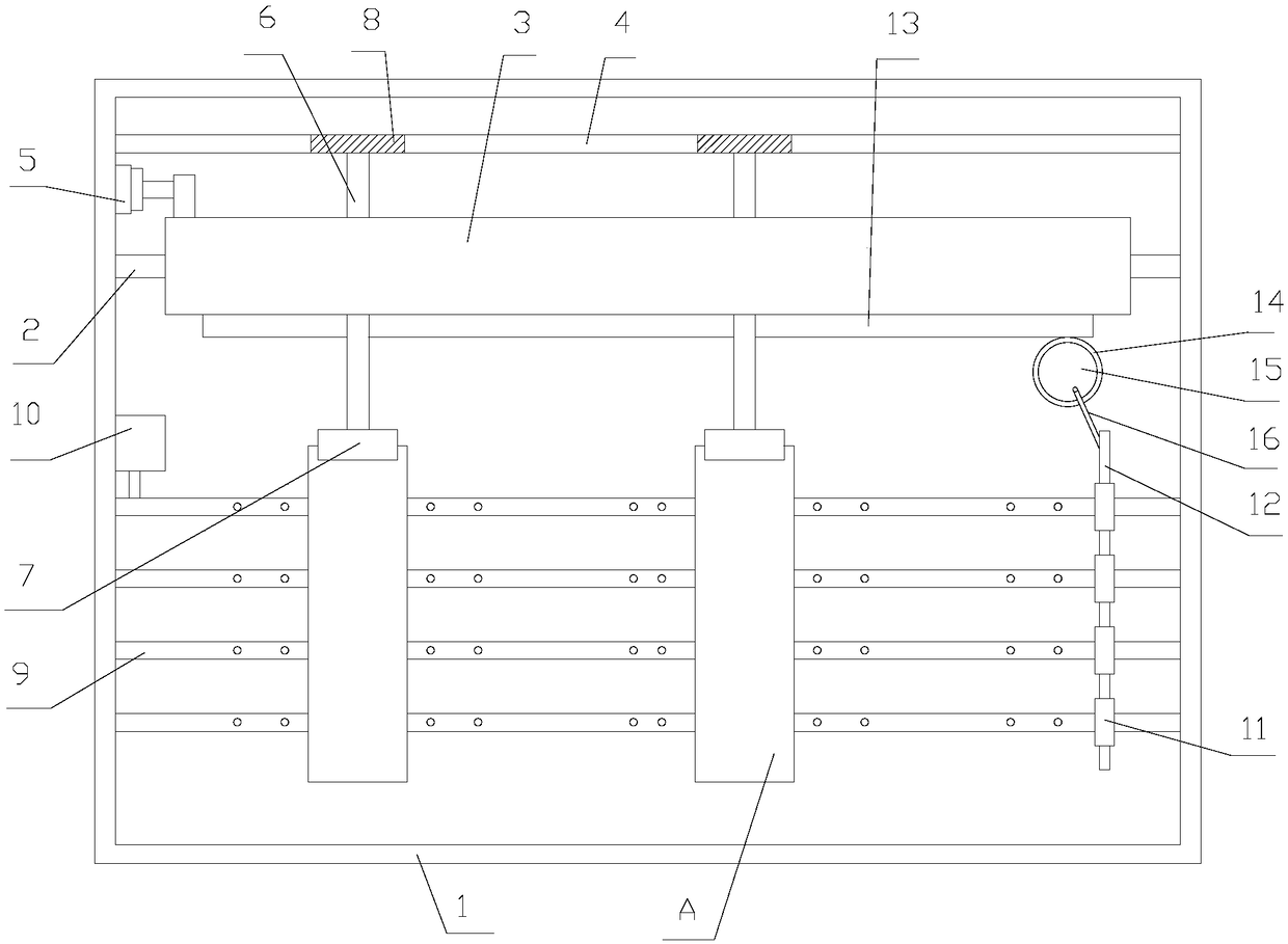
[0014] refer to figure 1 , a steel-backed drying device proposed by the present invention includes a box body 1, a support portion positioned inside the box body 1, and a drying portion positioned inside the box body 1, and the support portion includes a slide bar 2, a moving plate 3, a plurality of The support unit, the first rack 4, the drive unit 5, the slide bar 2 is connected to the box body 1; the moving plate 3 is slidably connected to the slide bar 2; a plurality of support units are distributed sequentially along the length direction of the slide bar 2, and the support unit includes a support Rod 6, clamping assembly 7, first gear 8, pole 6 is rotationally co...


PUM


Abstract

The invention discloses a steel backing drying unit which comprises a box, a supporting part located on the inner side of the box and a drying part located on the inner side of the box. The supportingpart comprises a sliding rod, a moving plate, a plurality of supporting units, a first rack and a driving unit, and the sliding rod is connected with the box; the moving plate is in sliding connection with the sliding rod; the multiple supporting units are sequentially distributed in the length direction of the sliding rod; each supporting unit comprises a strut, a clamping assembly and a first gear; and the struts are rotationally connected with the moving plate. The clamping assemblies are installed on the struts, the first gears are installed on the struts, the first rack is connected withthe box and is parallel to the sliding rod, and the first rack is engaged with the first gears; and the driving unit is used for driving the moving plate to move, and the drying part is used for spraying out air.

Description

technical field [0001] The invention relates to the field of brake pads, in particular to a steel back drying device. Background technique [0002] Brake pads are generally composed of a steel back, an adhesive insulation layer and a friction block. The steel back needs to be painted to prevent rust. During the painting process, an SMT-4 furnace temperature tracker is used to detect the temperature distribution during the painting process to ensure quality. The heat insulation layer is composed of materials that do not conduct heat, and the purpose is heat insulation. The friction block is composed of friction material and adhesive, which is squeezed on the brake disc or brake drum to generate friction during braking, so as to achieve the purpose of vehicle deceleration and braking. Due to friction, the friction block will be gradually worn, generally speaking, the lower the cost of the brake pads, the faster the wear. [0003] In the production of brake pads, cleaning is ...

Claims


Application Information

Patent Timeline
IPC IPC(8): F26B9/06F26B21/00F26B25/00
CPCF26B9/06F26B21/004F26B25/00
Inventor 林和平
Owner ANHUI GUIDA AUTO PARTS
Why Eureka
Try Eureka