Lifting appliance structure with moving and locking function

A spreader and functional technology, applied in the spreader field, can solve problems such as unsafe lifting

Inactive Publication Date: 2018-10-26
长兴新亚环保机械科技股份有限公司
View PDF0 Cites 1 Cited by
  • Summary
  • Abstract
  • Description
  • Claims
  • Application Information

AI Technical Summary

Problems solved by technology

[0002] When transporting materials in the construction industry, spreaders are usually used for lifting. When traditional spreaders are used, they use wire ropes to lift the bundled materials. This method makes it easier for materials to be transported during transportation. It rotates and swings along the length of the wire rope, and at the same time, it is unsafe to lift. For this reason, a spreader structure with moving and locking functions is required.

Method used


Image

  • Lifting appliance structure with moving and locking function
  • Lifting appliance structure with moving and locking function
  • Lifting appliance structure with moving and locking function

Examples


Embodiment Construction

[0019] The following will clearly and completely describe the technical solutions in the embodiments of the present invention with reference to the accompanying drawings in the embodiments of the present invention. Obviously, the described embodiments are only some, not all, embodiments of the present invention.

[0020] In describing the present invention, it should be understood that the terms "center", "longitudinal", "transverse", "length", "width", "thickness", "upper", "lower", "front", " Orientation indicated by rear, left, right, vertical, horizontal, top, bottom, inside, outside, clockwise, counterclockwise, etc. The positional relationship is based on the orientation or positional relationship shown in the drawings, and is only for the convenience of describing the present invention and simplifying the description, rather than indicating or implying that the referred device or element must have a specific orientation, be constructed and operated in a specific orientat...


PUM


Abstract

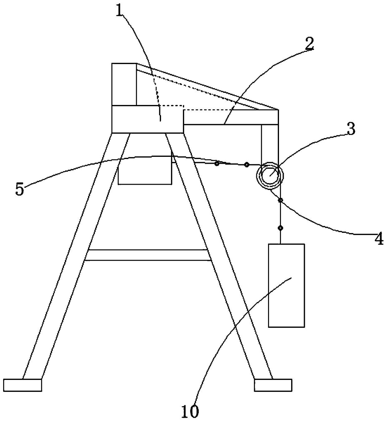
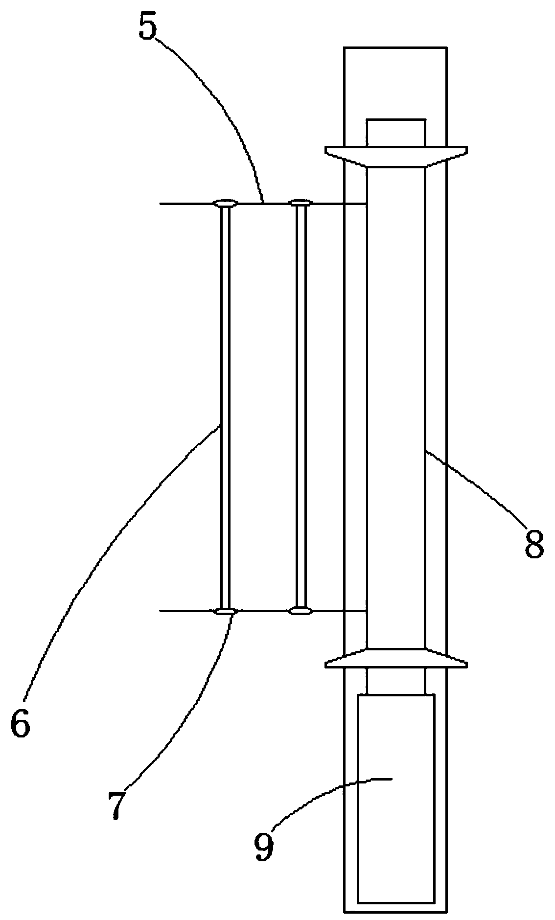
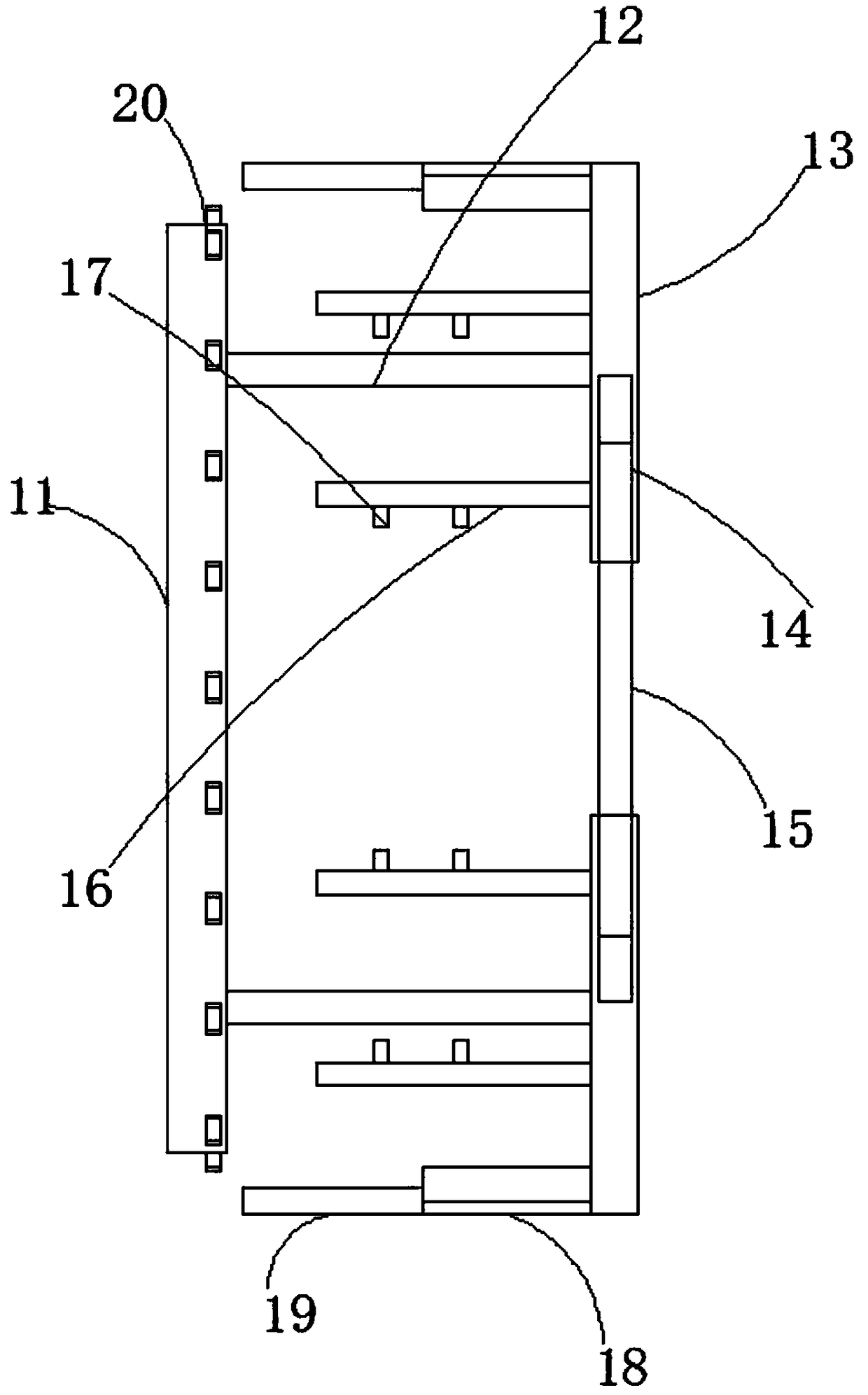
The invention discloses a lifting appliance structure with a moving and locking function. The lifting appliance structure comprises a transverse beam, a supporting plate is fixedly connected to one side of the transverse beam, a support of a U-shaped structure is fixedly connected to the bottom of the end, far away from the transverse beam, of the supporting plate, the bottom of the support is movably sleeved with two sets of sliding wheels, the outer rings of the two sets of the sliding wheels are sleeved with steel wire ropes in a sliding manner, holding rods are installed between the two sets of steel wire ropes in the length direction of the steel wire ropes at equal intervals, the two ends of the holding rods are fixedly connected with guide rollers fixedly connected to the steel wireropes in a sleeve manner, one ends of the steel wire ropes are connected with winding rollers connected with the bottom of the transverse beam, one ends of the winding rollers are provided with driving motors fixedly connected with the bottoms of the transverse beam, and the other ends of the steel wire ropes are connected with clamping mechanisms. The lifting appliance structure is simple in structure and convenient and quick in operation, is suitable for lifting materials with different lengths and quantities, meanwhile, enables the materials to be firmly bound in the lifting process, and effectively avoids rotation swing of the materials in the steel wire rope length direction during lifting.

Description

technical field [0001] The invention relates to the technical field of spreaders, in particular to a spreader structure with moving and locking functions. Background technique [0002] When transporting materials in the construction industry, spreaders are usually used for lifting. When traditional spreaders are used, they use wire ropes to lift the bundled materials. This method makes it easier for materials to be transported during transportation. It rotates and swings along the length direction of the wire rope, and at the same time, it is unsafe to lift. For this reason, a spreader structure with moving and locking functions is needed. Contents of the invention [0003] The purpose of the present invention is to solve the shortcomings in the prior art, and propose a spreader structure with moving and locking functions. [0004] In order to achieve the above object, the present invention adopts the following technical solutions: [0005] A spreader structure with movi...

Claims


Application Information

Patent Timeline
Patent Type & Authority Applications(China)
IPC IPC(8): B66D3/20B66D3/26
CPCB66D3/20B66D3/26
Inventor 马浩舟
Owner 长兴新亚环保机械科技股份有限公司
Why Eureka
Try Eureka