
Locking connecting mechanism for bus groove assembly production line

A connection mechanism and busway technology, applied in metal processing, metal processing equipment, manufacturing tools, etc., can solve problems such as potential safety hazards, inability to meet the needs of intelligent automatic control, and cumbersome processes

Pending Publication Date: 2018-10-26
ZHENJIANG SCHNEIDER ELECTRIC
View PDF0 Cites 0 Cited by
  • Summary
  • Abstract
  • Description
  • Claims
  • Application Information

AI Technical Summary

Problems solved by technology

[0002] Busway products are the key equipment in power transmission and distribution products in the power industry. Traditional busway products are composed of side panels and cover plates that are manually assembled and fixed into the busway shell, with built-in phase conductors. Busway side panels and cover panels , phase line conductors are all metal materials, bulky and heavy, only simple fixtures are used to assist assembly during assembly, manual assembly is difficult, production efficiency is low, there are potential safety hazards, and it cannot adapt to the intelligent automatic control of the increasing development of science and technology at this stage In addition, the traditional busway is fastened and connected by bolts and nuts. The number of parts is large, and the bolts and nuts protrude from the surface of the busway product, which is inconvenient for packaging, handling, and installation operations; the busbar pneumatic assembly production line in the prior art can only One-way pressing, unreliable assembly accuracy, need to turn around during the assembly process, the process is cumbersome

Method used


Image

  • Locking connecting mechanism for bus groove assembly production line
  • Locking connecting mechanism for bus groove assembly production line
  • Locking connecting mechanism for bus groove assembly production line

Examples


Embodiment Construction

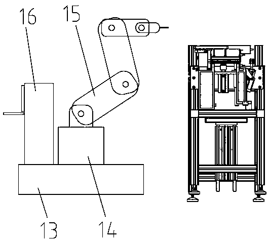
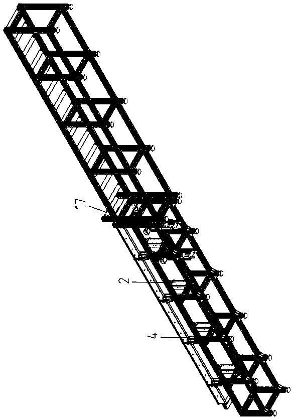
[0019] As shown in the figure, a locking connection mechanism for a bus duct assembly production line includes a chassis, which is divided into an assembly section 1 located in the front section and a conveying section 12 located in the rear section along the length direction. The conveyor section 12 chassis A number of horizontal conveying rollers 121 are arranged side by side and evenly distributed on the upper surface; on both sides of the upper part of the assembly section 1 are arranged a number of first limit support columns 2 and second limiters that can respectively limit and support the folded edges and side plates of the upper and lower cover plates of the bus duct products. The limit support column 4, the top of the first limit support column 2 is provided with a pressure rod 20, the pressure rod 20 extends laterally to the top of the busway product, and the pressure rod 20 is connected with a side plate capable of pressing the busway product from top to bottom. Pres...


PUM


Abstract

The invention discloses a locking connecting mechanism for a bus groove assembly production line. A chassis is divided into an assembly section and a conveying section; the assembly section uses a first limiting support column and a second limiting support column for limiting support of upper and lower cover plates and side plates of bus groove products; a pressing rod at the top end of the firstlimiting support column tightly presses the side plates of the bus groove products through a pressing foot from top to bottom; a first cylinder drives a Taiwan fixture to tightly press the cover plates of the bus groove products from the side surfaces; limiting support blocks limit the side plates, the cover plates and phase line modules of the bus groove products through limiting side plates andlimiting end plates; and an intelligent mechanical arm, a first cylinder and a second cylinder on an intelligent control cabinet interlocking control equipment base clamp and lock the side plates andthe cover plates of the bus groove products to fixedly rivet as overall bus groove products through rivets. The process is simple; the assembly operation is convenient; the assembly precision of the bus groove products is high; and the product quality consistency is excellent.

Description

technical field [0001] The invention relates to a locking connection mechanism for a busbar duct assembly production line. Background technique [0002] Bus duct products are key equipment in power transmission and distribution products in the power industry. Traditional bus duct products are composed of side plates and cover plates that are manually assembled and connected to the bus duct shell, with built-in phase conductors. Bus duct side plates and cover plates The conductors of the phase conductors are all metal materials, which are large and bulky. They are assembled only by simple fixtures during assembly. The manual assembly operation is difficult, the production efficiency is low, and there are potential safety hazards. In addition, the traditional bus duct is fastened and connected by bolts and nuts, the number of parts is large, and the bolts and nuts protrude from the surface of the bus duct, which is inconvenient for packaging, handling and installation operatio...

Claims


Application Information

Patent Timeline
Patent Type & Authority Applications(China)
IPC IPC(8): B23P19/00B23P19/02B21J15/10
CPCB21J15/10B23P19/00B23P19/001B23P19/02
Inventor 陈跃宏
Owner ZHENJIANG SCHNEIDER ELECTRIC
Learn More