
Plate and bolt riveting mechanism

A riveting mechanism and bolt technology, which is applied in the field of processing equipment for iron sheet products, can solve the problems of low riveting efficiency, consuming riveting man-hours, unfavorable low-cost large-scale production, etc., and achieve the effect of improving efficiency, reducing man-hours, and ejecting materials Good results

Active Publication Date: 2018-10-26
XUZHOU SHUODING MASCH MFG CO LTD
View PDF5 Cites 0 Cited by
  • Summary
  • Abstract
  • Description
  • Claims
  • Application Information

AI Technical Summary

Problems solved by technology

[0007] At present, most of the riveting of this kind of products is manual riveting. First, the two plates are butted and limited, and then the hollow bolts are manually driven into the butt holes of the two plates to complete the riveting connection of this type of product. The riveting efficiency of this kind of manual operation is low, and it can only be limited and riveted one at a time, which consumes a lot of riveting man-hours, which is not conducive to low-cost large-scale production

Method used


Image

  • Plate and bolt riveting mechanism
  • Plate and bolt riveting mechanism
  • Plate and bolt riveting mechanism

Examples


Embodiment Construction

[0037] In order to enable those skilled in the art to better understand the technical solution of the present invention, the present invention will be described in detail below in conjunction with the accompanying drawings. The description in this part is only exemplary and explanatory, and should not have any limiting effect on the protection scope of the present invention. .

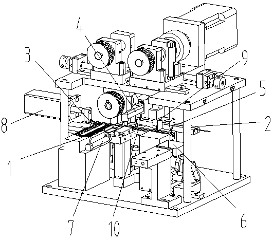
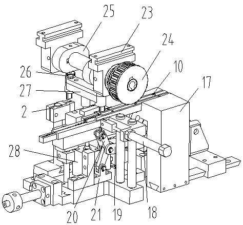
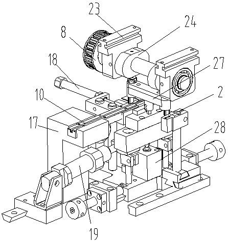
[0038] Such as Figure 1-Figure 8 As shown, the specific structure of the present invention is: a riveting mechanism for plates and bolts, which includes a support plate, on which the left and right riveting delivery troughs 10 are arranged through mounting seats 17, and the riveting delivery troughs 10 The left end is provided with the lower plate feeding device matched with it, the lower part is provided with the riveted bolt conveying trough 3 matched with it, the upper plate feeding device matched with it is arranged above, and the material receiving box 6 matched with it is provided at the right e...


PUM


Abstract

The invention relates to the field of machining equipment of iron sheet products, in particular to a plate and bolt riveting mechanism. The plate and bolt riveting mechanism comprises a supporting plate, a left riveting conveying groove and a right riveting conveying groove are formed in the supporting plate through a mounting base, a lower plate feeding device matched with the riveting conveyinggroove is arranged at the left end of the riveting conveying groove, a riveting bolt conveying groove matched with the riveting bolt conveying groove is formed in the lower portion, the riveting conveying groove is provided with an upper plate feeding device matched with the upper plate feeding device, a receiving box matched with the upper plate feeding device is arranged at the right end of theupper plate feeding device, the material receiving box is connected with a material receiving air cylinder in the front-back direction, a pushing device matched with the riveting bolt conveying grooveis arranged at the tail end of the riveting bolt conveying groove, and a riveting opening matched with the riveting conveying groove is formed in the bottom of the riveting conveying groove right above the ejecting device; the riveting bolt is jacked into the riveting conveying groove through the jacking device and is matched with the hole positions of the two plates, riveting machining is completed, riveting efficiency is greatly improved, and riveting time is reduced.

Description

[0001] Original application number: 2016112183591 [0002] Applicant of the original case: Dongguan Ronggong Automation Technology Co., Ltd. [0003] Date of original filing: December 26, 2016 [0004] Title of original application: A riveting device for iron sheet products. technical field [0005] The invention relates to the field of processing equipment for iron sheet products, in particular to a riveting mechanism for plates and bolts. Background technique [0006] In iron sheet products, an iron sheet product consisting of an upper plate and a lower plate is often used, and the upper plate and the lower plate are riveted and connected by a hollow bolt matching them. [0007] At present, most of the riveting of this kind of products is manual riveting. First, the two plates are butted and limited, and then the hollow bolts are manually driven into the butt holes of the two plates to complete the riveting connection of this type of product. The riveting efficiency of ...

Claims


Application Information

Patent Timeline
Patent Type & Authority Applications(China)
IPC IPC(8): B21J15/10B21J15/18B21J15/32B21J15/38
CPCB21J15/10B21J15/18B21J15/32B21J15/38
Inventor 邓君黄红梅
Owner XUZHOU SHUODING MASCH MFG CO LTD
Learn More