
Gas ultrasonic flow sensor

A flow sensor and ultrasonic technology, applied in the field of sensors, can solve problems such as slow response, failure, and rapid aging of glue, and achieve the effects of improved external impact resistance, stable solid-sealing structure, and good sealing performance

Inactive Publication Date: 2018-10-19
四川菲罗米特仪表有限公司
View PDF8 Cites 1 Cited by
  • Summary
  • Abstract
  • Description
  • Claims
  • Application Information

AI Technical Summary

Problems solved by technology

However, there are mutual constraints on resolution, sensitivity, and withstand voltage capability.
Moreover, most of the existing ultrasonic sensors adopt adhesive structure. Since the adhesive ages quickly and cannot solve the shear force caused by the expansion coefficient of each component, all thermal and cold changes will soon deglue and cause the sensor to fail.
Moreover, most of the existing ultrasonic sensors only form plane contact with the shell of the sensor. During long-term use, it is easy to cause phenomena such as poor sealing and moisture, resulting in low sensitivity of the piezoelectric element and slow response speed. This will affect the reliability and service life of the ultrasonic flow sensor

Method used


Image

  • Gas ultrasonic flow sensor

Examples


Embodiment Construction

[0023] The technical solutions in the embodiments of the present invention will be clearly and completely described below in conjunction with the drawings in the embodiments of the present invention. Obviously, the described embodiments are only part of the embodiments of the present invention, not all of them. Based on the embodiments of the present invention, all other embodiments obtained by persons of ordinary skill in the art without making creative efforts fall within the protection scope of the present invention.

[0024] It should be noted that all directional indications (such as up, down, left, right, front, back...) in the embodiments of the present invention are only used to explain the relative relationship between the various components in a certain posture (as shown in the figure). When the positional relationship, movement conditions, etc., if the specific posture changes, the directional indication will also change accordingly.

[0025] In addition, the descri...


PUM


Abstract

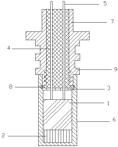
The invention discloses a gas ultrasonic flow sensor. The gas ultrasonic flow sensor comprises a shell, a piezoelectric unit, a matching piece, a lining plate and a potting adhesive, wherein the matching piece is fixedly arranged at the inner side of the bottom part of the shell; the piezoelectric unit is fixedly connected with the matching piece; the lining plate is supported in the shell and isused for dividing the inner part of the shell into a sealing zone and a working zone; the matching piece and the piezoelectric unit are located under the lining plate and in the working zone; the potting adhesive is arranged in the sealing zone in a potting way and is located on the surface of the lining plate; the lining plate, the piezoelectric unit and the matching piece are fixedly arranged inthe shell by the potting adhesive in a sealing way; a signal line upward penetrates through the lining plate and the potting adhesive from the piezoelectric unit and stretches out of the shell; the lining plate and the piezoelectric unit are in clearance fit in a vertical direction of the inner part of the shell, and an air layer is formed between the lining plate and the piezoelectric unit. Thegas ultrasonic flow sensor disclosed by the invention is large in structural strength and good in sealing performance, and is capable of effectively ensuring fixing and sealing on the piezoelectric element and solving a shear force brought by expansion coefficients of all components; the original resolution ratio of a product cannot be reduced while the sensitivity is improved.

Description

technical field [0001] The invention relates to the technical field of sensors, in particular to a gas ultrasonic flow sensor. Background technique [0002] Ultrasonic flowmeter is a device for measuring the flow of gas, liquid and other fluids, and ultrasonic sensor is one of the key components of ultrasonic flowmeter. When the ultrasonic sensor works, it needs to provide a specific oscillating signal from an external power supply. The sensor receives the oscillating signal and converts it into an ultrasonic wave, and then the sensor transmits it into the air; on the contrary, the sensor receives the ultrasonic signal in the air and converts it into a specific electrical signal and transmits it to the system. . [0003] In the prior art, the function of the existing ultrasonic sensor is to convert mechanical energy into electrical energy, that is to say, to convert the ultrasonic signal in the form of pulse into an electrical pulse signal, which includes a casing and a sig...

Claims


Application Information

Patent Timeline
IPC IPC(8): G01F1/66
CPCG01F1/662
Inventor 赵辉山有元
Owner 四川菲罗米特仪表有限公司
Learn More