


Quick Research
Generate reliable direction feasibility study reports for your R&D in just a few steps.

Technical Q&A
Discover and master advanced knowledge NOW. Basics, ideas, possibilities, all at once.

Find Solutions
As an expert in R&D theories, this can generate solutions to your technical problems instantly.

Evaluate Feasibility
Analyze your overall solution with one click, know your potential R&D risks in advance.

Monitor Landscape
Get weekly tech updates, stay abreast of the latest tech innovations and key insights.
Light guide plate with hole structure
A light guide plate and technology with holes, applied in the field of light guide plates, can solve the problems that the optical visual effect is not easy to meet the requirements and affect light transmission, etc., and achieve the effect of maintaining consistent luminous effect, uniform luminous brightness, and increasing the density of light guide points
- Summary
- Abstract
- Description
- Claims
- Application Information
AI Technical Summary
Problems solved by technology
Method used
Image

Examples
Example Embodiment
[0020] Example 1
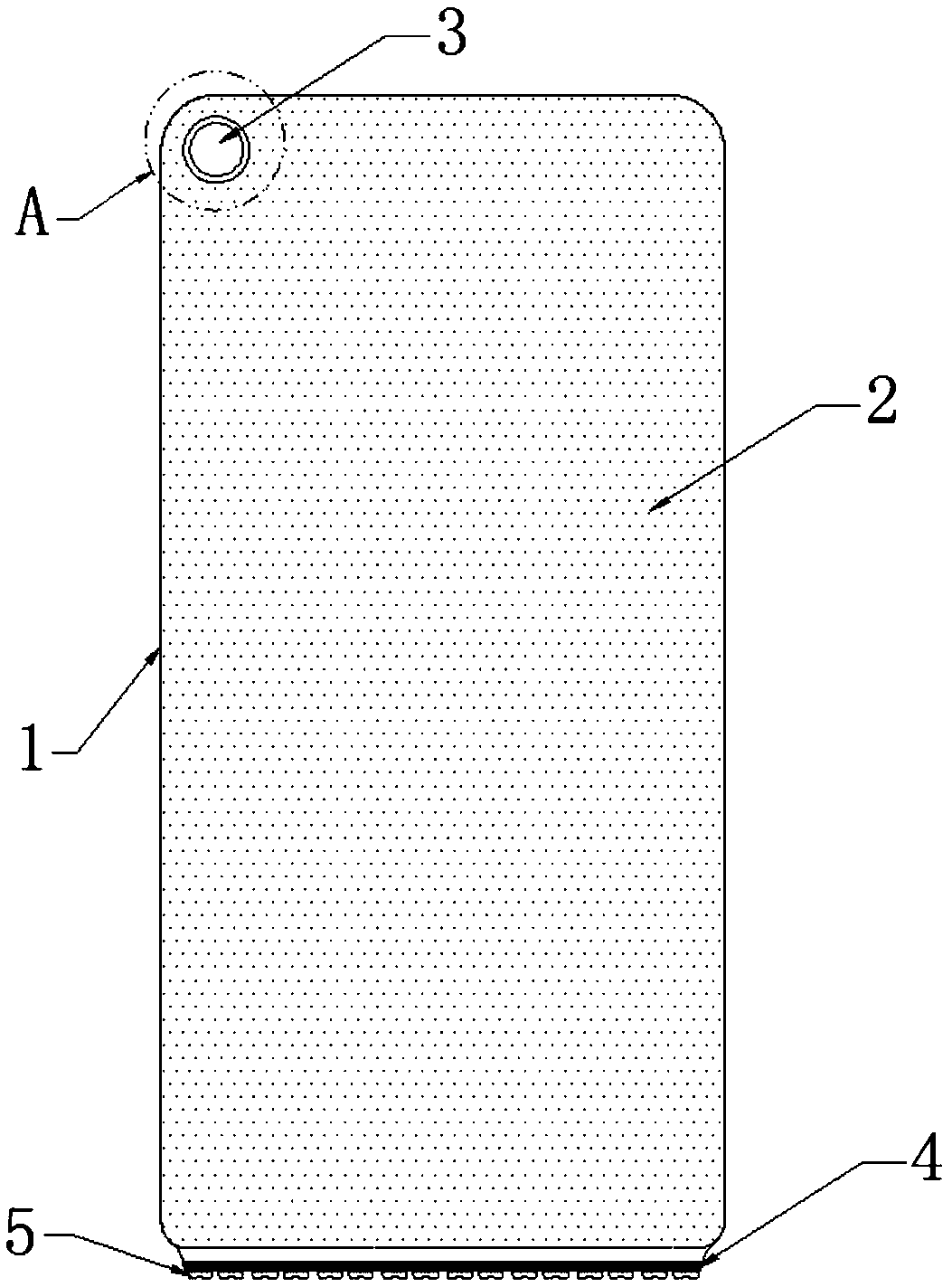
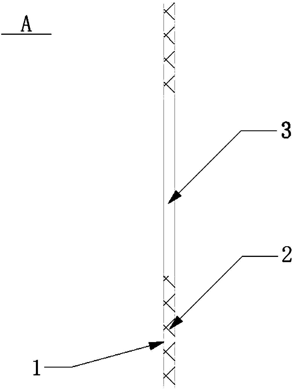
[0021] A light guide plate with a hole structure, the structure diagram of the light guide plate with a hole structure in this embodiment is as follows figure 1 As shown, the light guide plate body 1 and the light guide point 2 are included; the material of the light guide plate body 1 is iron. In the backlight source with the light guide plate, the bottom end is the light source incident direction, which corresponds to the light source installation position 4. The installation position 4 is equipped with an LED light strip 5 as a light source; the light guide point 2 is a light reflection microstructure distributed on the light guide plate body 1; a through hole 3 is opened on the top of the light guide plate body 1 near the edge;
[0022] Among them, such as figure 2 As shown, the through hole 3 is a circular through hole, and the position of the through hole 3 is located at the left side of the top end of the light guide plate body 1 near the edge.
[0023] Thr...
Example Embodiment
[0024] Example 2
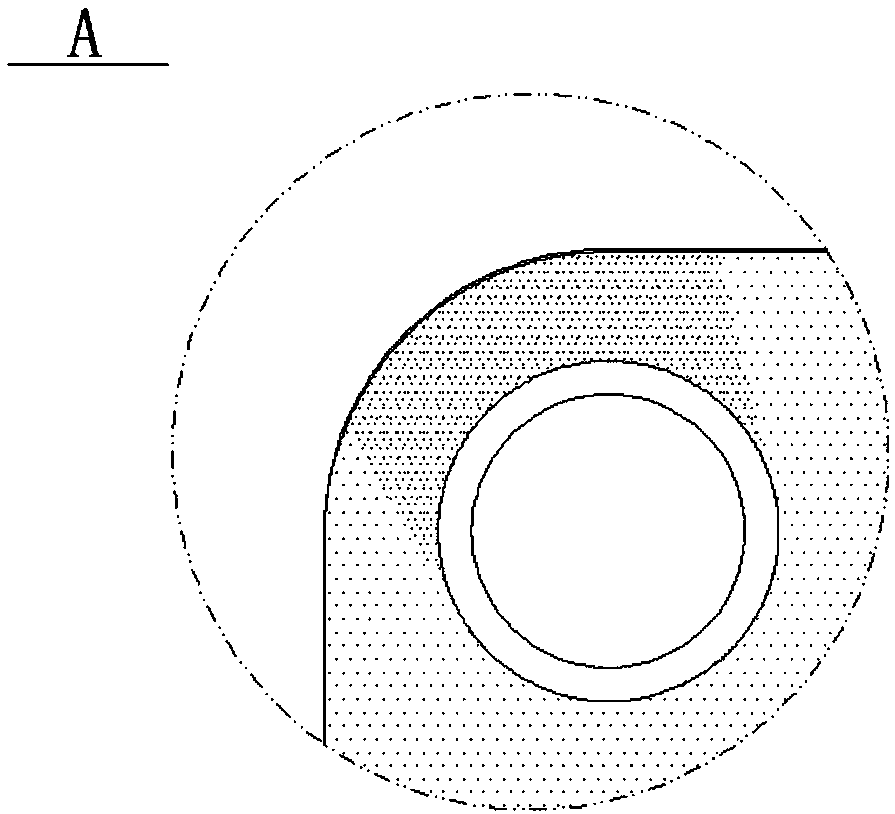
[0025] A light guide plate with a hole structure, such as image 3 As shown, on the side opposite to the light source of the through hole 3, the light guide points 2 are densely distributed, specifically: the distribution density of the light guide points 2 is greater than the distribution density of the light guide points 2 at any other position on the light guide plate body 1.
[0026] In this embodiment, the distribution of light guide points is adjusted near the edge of the perforated structure of the light guide plate, and the light guide point distribution rule near the opening position is adjusted to increase the light guide point density on the opposite side of the perforated light source, so that The overall light-emitting brightness of the light guide plate is uniform, so that the light-emitting effect at the opening is consistent with the light-emitting effect of the overall light guide plate, which can meet the requirements of high proportion of mobil...
PUM
 Abstract
Description
Claims
Application Information
 - R&D Engineer
- R&D Manager
- IP Professional
- Industry Leading Data Capabilities
- Powerful AI technology
- Patent DNA Extraction
Browse by: Latest US Patents, China's latest patents, Technical Efficacy Thesaurus, Application Domain, Technology Topic, Popular Technical Reports.
© 2024 PatSnap. All rights reserved.Legal|Privacy policy|Modern Slavery Act Transparency Statement|Sitemap|About US| Contact US: help@patsnap.com