
A multi-probe spherical near-field cross-polarization correction method

A multi-probe, near-field technology, applied in the direction of instruments, antenna radiation patterns, measuring devices, etc., to achieve the effects of easy software integration, simplified erection tooling requirements, and shortened erection and measurement time

Active Publication Date: 2020-06-09
BEIJING INST OF SPACECRAFT SYST ENG
View PDF4 Cites 0 Cited by
  • Summary
  • Abstract
  • Description
  • Claims
  • Application Information

AI Technical Summary

Problems solved by technology

This method is mainly used for polarization correction in antenna far-field measurement, single-probe spherical or planar near-field measurement. For multi-probe spherical near-field, since the probe polarization cannot be rotated, this method cannot be used for calibration

Method used


Image

  • A multi-probe spherical near-field cross-polarization correction method
  • A multi-probe spherical near-field cross-polarization correction method
  • A multi-probe spherical near-field cross-polarization correction method

Examples


Embodiment Construction

[0032] The present invention will be further described below in conjunction with the accompanying drawings.

[0033] A multi-probe spherical near-field cross-polarization correction method, comprising the following steps:

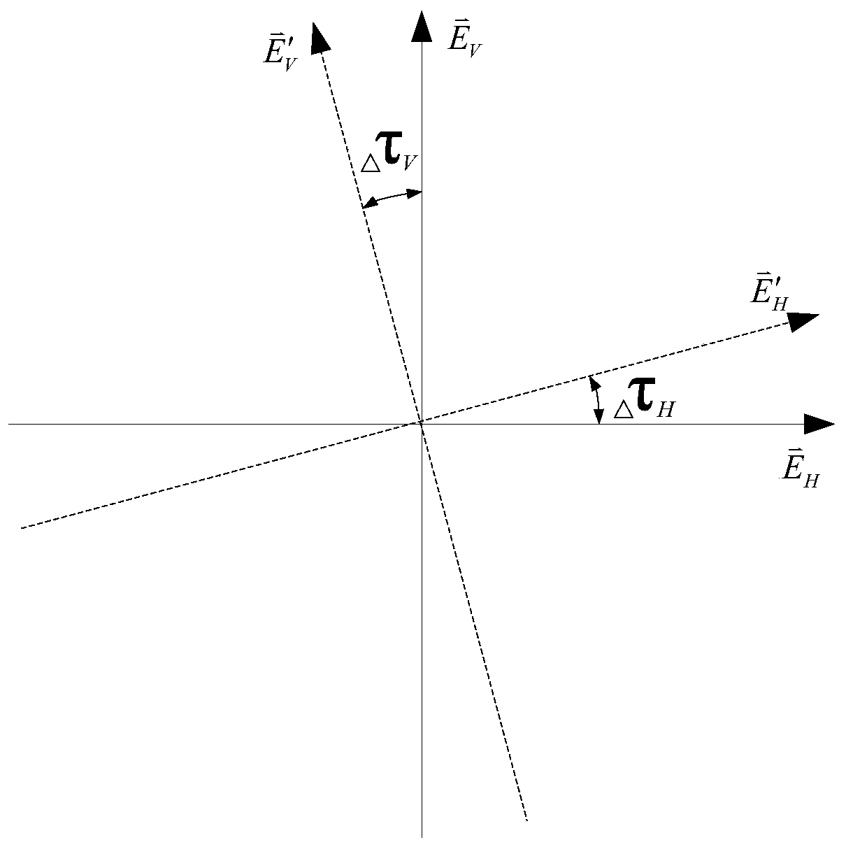
[0034] Step 1: Select an auxiliary antenna with a high cross-polarization ratio and a known polarization inclination angle. In order to ensure the measurement accuracy of the polarization deflection angle, the cross-polarization ratio of the auxiliary antenna should be better than 35dB. The working frequency band of the auxiliary antenna should cover all the frequency points to be measured by the antenna under test, and usually choose a pyramid horn antenna or a ridge horn antenna;

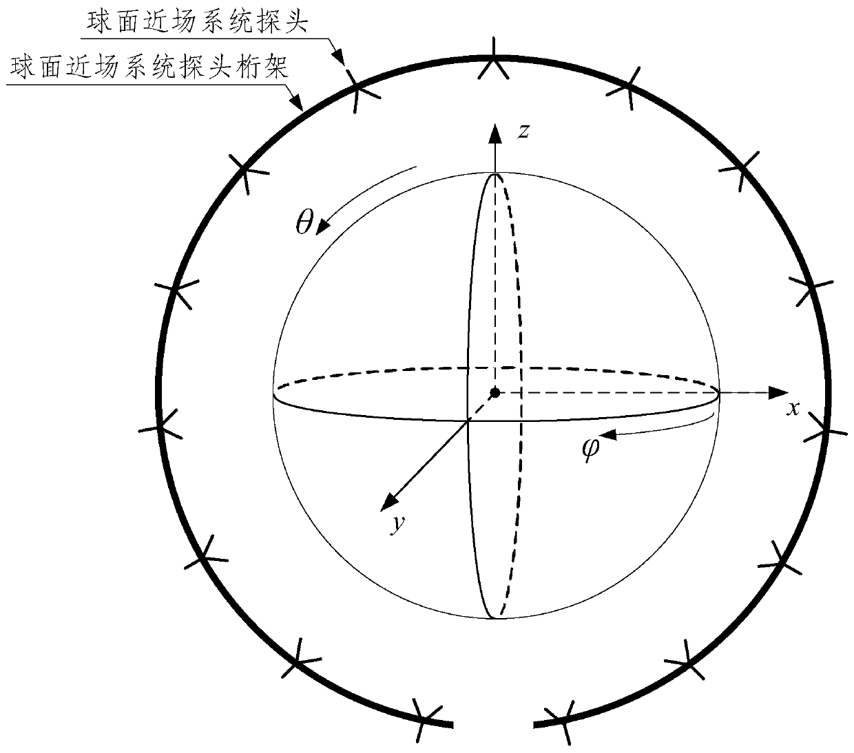
[0035] Step 2: Set up the auxiliary antenna at the origin of the coordinate system of the multi-probe spherical near-field measurement system, image 3 It is a schematic diagram of the coordinate system of the multi-probe spherical near-field measurement system. The coordinat...


PUM


Abstract

A multi-probe spherical near-field cross polarization correction method includes the following steps: step 1, calculating the polarization tilt angle measurement value of an auxiliary antenna and thepolarization tilt angle deviation of a multi-probe spherical near-field measurement system; step 2, performing radiation pattern measurement of an antenna under test to obtain cross polarization far-field pattern vector data and main polarization far-field pattern vector data of the antenna under test; and step 3, according to the polarization tilt angle deviation of the multi-probe spherical near-field measurement system obtained in step 1, and the measured cross polarization far-field pattern vector data and main polarization far-field pattern vector data of the antenna under test obtained in step 2, using the method of a polarization reference coordinate system to correct the cross polarization vector data to obtain corrected cross polarization data. The method calibrates the cross polarization level measured by the multi-probe spherical near field, and is suitable for accurate measurement of low cross polarization antennas such as mobile communication base station antennas and satellite borne communication antennas.

Description

technical field [0001] The invention relates to a multi-probe spherical near-field cross-polarization correction method. Background technique [0002] The rapid development of wireless communication technology provides great convenience for people's information communication. However, since the available wireless spectrum resources are limited, how to make full use of the existing spectrum bandwidth is an important research field. With the development of communication technology, a variety of techniques to improve spectrum utilization have been developed, such as frequency diversity, time diversity, space diversity, and polarization diversity. The first three kinds of diversity achieve diversity by sacrificing bandwidth, time and space, and the communication efficiency and space utilization are low. The most widely used polarization diversity is dual polarization diversity, that is, the same frequency is used to transmit two wireless signals whose polarization directions a...

Claims


Application Information

Patent Timeline
Patent Type & Authority Patents(China)
IPC IPC(8): G01R29/10G01R35/00
CPCG01R29/10G01R35/005
Inventor 李海良周怀安姜华陈雷樊勇张晓平苏浩陈军郭杰单金柱
Owner BEIJING INST OF SPACECRAFT SYST ENG
Learn More