Automatic gas nail assembling equipment with high safety performance

A safety performance, automatic assembly technology, applied in metal processing equipment, metal processing, manufacturing tools, etc., can solve the problems of operator injury, damage, large volume, etc., to achieve the effect of improving stability and performance

Pending Publication Date: 2018-10-16
杜成森
View PDF0 Cites 3 Cited by
  • Summary
  • Abstract
  • Description
  • Claims
  • Application Information

AI Technical Summary

Problems solved by technology

[0004] However, the existing gas nail automatic assembly equipment is not only complex in structure, but also has a single function. Because the gas nail automatic assembly equipment is in normal operation, the cylinder is continuously stretched and stretched, and the gas nail automatic assembly equipment has no function to protect the personal safety of the operator. , so that when the operator adds gas nails to the feed plate, his limbs are likely to collide with the telescopic rod of the cylinder, which makes it easy to cause damage to the operator's limbs when the cylinder is reciprocating; the automatic assembly equipment commonly used for gas nails is in After the gas nails are installed inside the rubber strips, they are only moved to one side of the worktable, which requires manual picking. Manual picking is not only time-consuming and laborious, but also in the case of normal operation of the automatic assembly equipment. Injuries to the limbs; due to the large volume and heavy weight of the automatic gas nail assembly equipment, in order to facilitate the movement, the bottom of the automatic gas nail assembly equipment is equipped with universal wheels, but the structure of the universal wheels cannot meet the requirements. The stability required for the automatic assembly of gas nails during normal work makes the automatic assembly of gas nails prone to shaking during normal work

Method used


Image

  • Automatic gas nail assembling equipment with high safety performance
  • Automatic gas nail assembling equipment with high safety performance
  • Automatic gas nail assembling equipment with high safety performance

Examples


Embodiment Construction

[0027] The following will clearly and completely describe the technical solutions in the embodiments of the present invention with reference to the accompanying drawings in the embodiments of the present invention. Obviously, the described embodiments are only some, not all, embodiments of the present invention. Based on the embodiments of the present invention, all other embodiments obtained by persons of ordinary skill in the art without making creative efforts belong to the protection scope of the present invention.

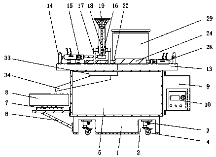
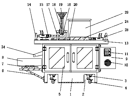
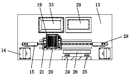
[0028] see Figure 1-7, the present invention provides a technical solution: an automatic assembly equipment for gas nails with high safety performance, including a pressure bearing 1, a groove 2 is opened on the lower surface of the pressure bearing 1, and the inner top of the groove 2 is fixedly installed There is an electro-hydraulic rod 3, the lower end of the electro-hydraulic rod 3 is fixedly equipped with a universal wheel 4, the upper surface of the pr...


PUM


Abstract

The invention discloses automatic gas nail assembling equipment with high safety performance. The automatic gas nail assembling equipment comprises a pressure-bearing support, electric hydraulic rodsare fixedly installed at the top ends in grooves, a pressure sensor is fixedly installed on the upper surface of a supporting frame, a photoelectric protector is fixedly installed on the upper surfaceof a working table top, a collecting groove is formed at one side, close to of a storage tank, of the upper surface of the working table top, and a discharging tank is fixedly connected to the lowersurface of the colleting groove. Through the photoelectric protector, when the automatic gas nail assembling equipment operates normally, the personal safety of operators can be effectively protected;through the collecting groove, the discharging tank and a receiving box, assembled gas nails can be collected; and through the electric hydraulic rods, the normal working stability of the automatic gas nail assembling equipment can be further improved on the premise of not affecting normal moving of the automatic gas nail assembling equipment.

Description

technical field [0001] The invention relates to the field of automatic assembly, in particular to automatic assembly equipment for gas nails with high safety performance. Background technique [0002] Automated assembly refers to an assembly technology that replaces manual labor with automated machinery. Automated assembly technology uses robots as assembly machinery and requires flexible peripheral equipment. [0003] In the assembly process, automated assembly can complete the following forms of operations: parts transmission, positioning and connection; use press fitting or fastening screws, nuts to fix parts to each other; assembly size control and ensure the quality of parts connection or fixing; conveying The assembled parts or products are packaged or stacked in containers, etc. Gas nails are a kind of nails used by gas nail guns. The assembly of gas nails needs to be completed by automatic assembly equipment. [0004] However, the existing gas nail automatic assembl...

Claims


Application Information

Patent Timeline
Patent Type & Authority Applications(China)
IPC IPC(8): B23P19/00
CPCB23P19/00B23P19/004
Inventor 尹瑞安杜成森
Owner 杜成森
Why Eureka
Try Eureka