Hydraulic engineering desilting device with stirring function and desilting method thereof

A technology for water conservancy projects and dredging devices, which is applied to mechanically driven excavators/dredgers, earthmoving machines/shovels, construction, etc., which can solve the problems of unfavorable miniaturization, inability to adjust the dredging depth, and inconvenience and flexibility. Mobile usage, etc.

Inactive Publication Date: 2018-10-12
李建州 +6
View PDF6 Cites 3 Cited by
  • Summary
  • Abstract
  • Description
  • Claims
  • Application Information

AI Technical Summary

Problems solved by technology

Existing problems: (1) Both the mud pump and the agitator have their own motors, which are heavy and need to be installed on the dredging ship, which is inconvenient to move and use flexibly, and is not conducive to miniaturization. It is only suitable for large-scale dredging sites
(2) High energy consumption
[0004] However, the above-mentioned scheme has the following defects in use: in the cleaning process, the dredging depth cannot be adjusted with the ups and downs of the silt, and the silt at a certain depth can only be cleaned, and the depth exceeds the depth of the detachable short pipe installed for the first time. After the total length, it will be difficult to meet the dredging requirements

Method used


Image

  • Hydraulic engineering desilting device with stirring function and desilting method thereof
  • Hydraulic engineering desilting device with stirring function and desilting method thereof
  • Hydraulic engineering desilting device with stirring function and desilting method thereof

Examples


Embodiment Construction

[0026] The technical solutions in the embodiments of the present invention will be clearly and completely described below in conjunction with the embodiments of the present invention. Apparently, the described embodiments are only some of the embodiments of the present invention, not all of them. Based on the embodiments of the present invention, all other embodiments obtained by persons of ordinary skill in the art without making creative efforts belong to the protection scope of the present invention.

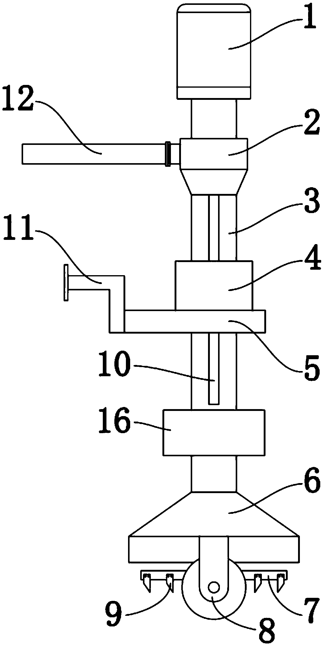
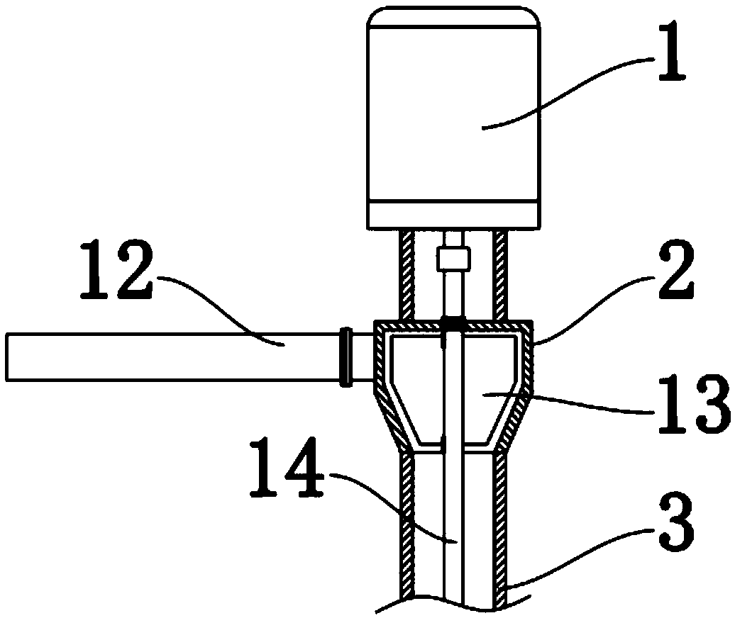
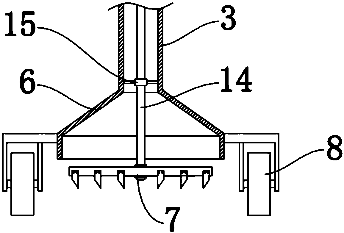
[0027] Such as Figure 1-4 As shown, a water conservancy dredging device with stirring function includes a fixed pipe 3 and a fixed plate 5, a motor 1 is installed on the top of the fixed pipe 3, and the output end of the motor 1 is fixedly connected with a Shaft 14, the bottom of the shaft 14 is pinned and fixed with a stirring rod 7, the fixed sleeve 4 is welded and fixed on the fixed plate 5, a connecting seat 11 is welded and fixed on one side of the fixed plate 5, the fi...


PUM


Abstract

The invention discloses a hydraulic engineering desilting device with a stirring function and a desilting method thereof. The desilting device comprises a fixed pipe and a fixed plate; a motor is mounted at the top end of the fixed pipe; an output end of the motor is fixedly connected with a shaft rod through a coupling; the bottom of the shaft rod is fixedly pinned with a stirring rod; a fixed sleeve is fixedly welded on the fixed plate; a connecting base is fixedly welded on one side of the fixed plate; the fixed pipe penetrates through the internal of the fixed sleeve; an impeller bin is arranged at the upper part of the fixed pipe; one side of the impeller bin is connected with a dirt discharge pipe through a flange; a dirt sucking cover is fixedly welded at the bottom end of the fixedpipe; and walking wheels are mounted on the two sides of the dirt sucking cover. The device uses the motor for driving the shaft rod to synchronously drive a stirring rod and an impeller to rotate, achieves multiple purposes by one machine, can be automatically adjusted according to the sludge depth to adapt to cleaning of sludge in different water depth places, and can realize flexible movementin areas through cooperation with movement of a desilting ship body to finish the sludge cleaning work in appointed areas.

Description

technical field [0001] The invention belongs to the technical field of water conservancy engineering devices, in particular to a water conservancy dredging device with stirring function and a dredging method thereof. Background technique [0002] There are currently two main types of equipment used for dredging: one is a split hydraulic dredger, which is suitable for small and medium-sized dredging equipment; the other is a dredging ship, which belongs to large and medium-sized dredging equipment. The hydraulic desilting machine is composed of a bank clear water centrifugal pump and a mud pump with a buoy in the water. The role of the bank clear water pump is to flush and stir the dredging site with hydraulic power, so that the mud near the suction port of the mud pump will be in a suspended state, so that the mud pump can pump away the mud water (concentration ≤ 30%). The dredging ship equipment is composed of a mud pump installed on the ship and a mechanical agitator inst...

Claims


Application Information

Patent Timeline
IPC IPC(8): E02F3/88E02F3/92
CPCE02F3/8875E02F3/9268
Inventor 李建州艾秀霞曾子武丁传发葛良义刘丽萍石琴
Owner 李建州
Why Eureka
Try Eureka