
Lifting device used for wind power equipment

A lifting device, wind power equipment technology, applied in the direction of transportation and packaging, load hanging components, etc., can solve the problems of low production efficiency, occupied driving, difficult operation, etc.

Inactive Publication Date: 2018-10-12
CHANGSHU GAOTONG INTELLECT EQUIP CO LTD
View PDF0 Cites 0 Cited by
  • Summary
  • Abstract
  • Description
  • Claims
  • Application Information

AI Technical Summary

Problems solved by technology

[0002] In the prior art, a girder hanger is usually used to lift the blade girder or web of wind power equipment. When hoisting the girder or web, the transfer vehicle must be moved to an area that can be reached by driving, and then a large or webs, hoisted to the transfer vehicle, and then powered by tractor or forklift for transfer, in the process of hoisting the hanger, the traffic must be occupied until a large amount or webs are hoisted on the transfer vehicle, and then the hanger Put it down, but this requires a lot of space in the workshop. When the workshop space is limited or the traffic is tight, such an operation is very difficult and the production efficiency is too low, and the girder hanger only undertakes the role of lifting, and it does not take much time. Use rate is low, for this reason, we propose a lifting device for wind power equipment to solve the above problems

Method used


Image

  • Lifting device used for wind power equipment
  • Lifting device used for wind power equipment
  • Lifting device used for wind power equipment

Examples


Embodiment Construction

[0017] The following will clearly and completely describe the technical solutions in the embodiments of the present invention with reference to the accompanying drawings in the embodiments of the present invention. Obviously, the described embodiments are only some, not all, embodiments of the present invention.

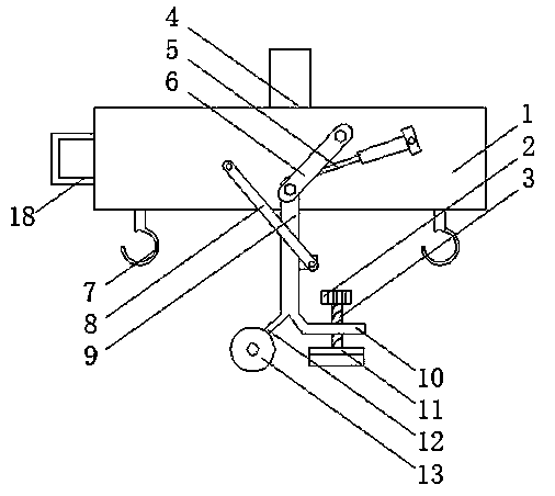
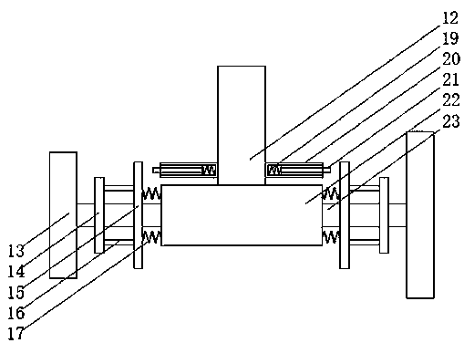
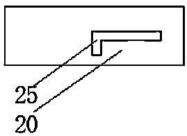
[0018] refer to Figure 1-4 , a lifting device for wind power equipment, including a hanger assembly 1, the upper end of the hanger assembly 1 is fixed with a crane ring 4, the crane ring 4 can fix the hanger assembly 1 on the crane, the lower end of the hanger assembly 1, etc. The distance is provided with a hook assembly 7, the hook assembly 7 can fix the girder of the wind power equipment for transportation, one side of the hanger assembly 1 is connected to the electric telescopic rod 5 in rotation, and the end of the electric telescopic rod 5 is fixed with the first rotating rod 6 , the electric telescopic rod 8 can push the first rotating rod 6, the upper end of...


PUM


Abstract

The invention discloses a lifting device used for wind power equipment. The lifting device comprises a lifting frame assembly, wherein the upper end of the lifting frame assembly is fixedly equipped with a crane lifting ring; the lower end of the lifting frame assembly is equipped with hanger assemblies at equal distance; one side of the lifting frame assembly is rotatably connected with an electric telescopic pole; the tail end of the electric telescopic pole is fixedly equipped with a first rotary rod; the upper end of the first rotary rod is rotatably connected on the lifting frame assembly; the lower end of the first rotary rod is rotatably connected with a fixed rod; one side of the lifting frame assembly is rotatably connected with a second rotary rod; and one end of the second rotary rod is rotatably connected on the fixed rod. The lifting device realizes lifting a blade girder or web of wind power equipment, can take down the lifting frame, moves the lifting frame to a place with a relatively great space, further can fix the lifting frame assembly, prevents the lifting frame assembly from shaking to move to injure people or other things, solves the problem that workshop space is occupied by an existing lifting beam group, and is suitable for being popularized.

Description

technical field [0001] The invention relates to the technical field of lifting devices, in particular to a lifting device for wind power equipment. Background technique [0002] In the prior art, a girder hanger is usually used to lift the blade girder or web of wind power equipment. When hoisting the girder or web, the transfer vehicle must be moved to an area that can be reached by driving, and then a large or webs, hoisted to the transfer vehicle, and then powered by tractor or forklift for transfer, in the process of hoisting the hanger, the traffic must be occupied until a large amount or webs are hoisted on the transfer vehicle, and then the hanger Put it down, but this requires a lot of space in the workshop. When the workshop space is limited or the traffic is tight, such an operation is very difficult and the production efficiency is too low, and the girder hanger only undertakes the role of lifting, and it does not take much time. Use Therefore, we propose a lifti...

Claims


Application Information

Patent Timeline
IPC IPC(8): B66C1/10B66C13/06
CPCB66C1/108B66C13/06
Inventor 钱理
Owner CHANGSHU GAOTONG INTELLECT EQUIP CO LTD
Learn More