
Locking device

A technology of locking device and locking end, which is applied to locomotives and other directions, can solve the problems of lock cylinder being greasy with sand and dust, time-consuming and labor-intensive, handwheel cannot be rotated, etc., and achieves fewer turns of rotation, wide adaptability and reliable installation Effect

Pending Publication Date: 2018-10-09
BEIJING CENTURY DONGFANG COMMUNICATION EQUIPMENT CO LTD
View PDF0 Cites 0 Cited by
  • Summary
  • Abstract
  • Description
  • Claims
  • Application Information

AI Technical Summary

Problems solved by technology

[0004] However, the structure of this locking mechanism is not flexible enough, and it takes time and effort to fix the tail device on the train; when the cast hole wall of the coupler is thin, the car body cannot be hooked tightly; Bad, often the hand wheel cannot be rotated, the lock cylinder is greasy to death by sand and dust, resulting in the phenomenon that the train end device cannot be detached from the train

Method used


Image

  • Locking device
  • Locking device
  • Locking device

Examples


Embodiment Construction

[0026] The specific implementation manners of the present invention will be further described in detail below in conjunction with the accompanying drawings and embodiments. The following examples are used to illustrate the present invention, but are not intended to limit the scope of the present invention.

[0027] In describing the present invention, it should be understood that the terms "center", "longitudinal", "transverse", "length", "width", "thickness", "upper", "lower", "front", " Back", "Left", "Right", "Vertical", "Horizontal", "Top", "Bottom", "Inner", "Outer", "Clockwise", "Counterclockwise", "Axial", The orientation or positional relationship indicated by "radial", "circumferential", etc. is based on the orientation or positional relationship shown in the drawings, and is only for the convenience of describing the present invention and simplifying the description, rather than indicating or implying the referred device or element Must be in a particular orientatio...


PUM


Abstract

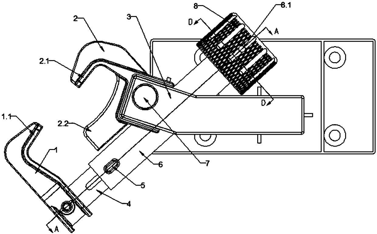
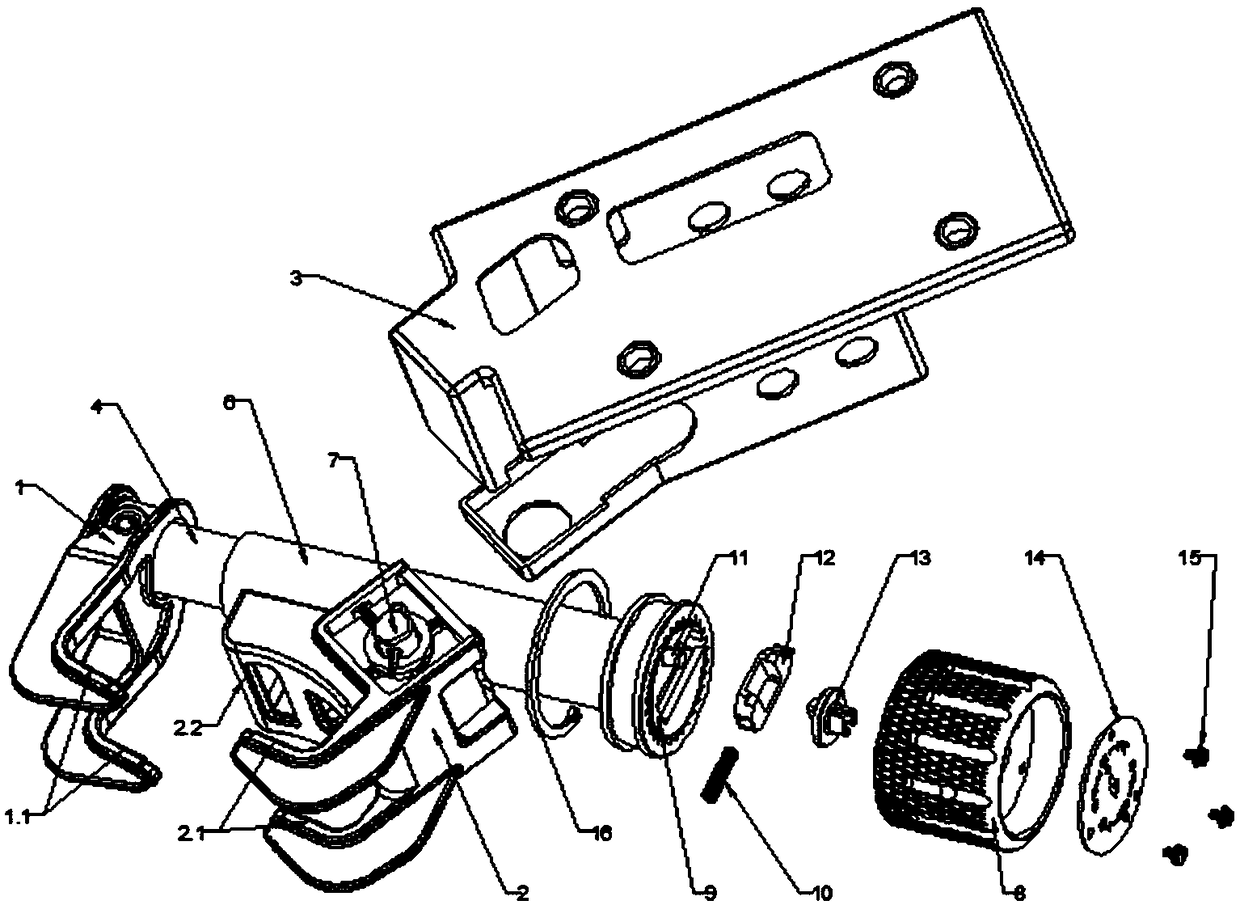
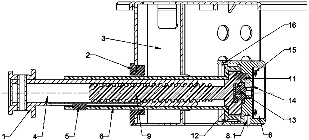
The invention relates to the technical field of locking and discloses a locking device. The locking device comprises an extending-retracting clamping hook, a rotary clamping hook, an extending-retracting mechanism and a locking mechanism. The connecting end of the extending-retracting clamping hook is connected with the extending-retracting end of the extending-retracting mechanism, and the connecting end of the rotary clamping hook is arranged between the extending-retracting end and the connecting end of the extending-retracting mechanism in a hinged mode; the extending-retracting clamping hook and the rotary clamping hook are arranged oppositely; and the connecting end of the extending-retracting mechanism is connected with the locking end of the locking mechanism, and the locking mechanism is used for locking the extending-retracting mechanism. According to the locking device, through hooking force from inside to outside provided by hook tips of the extending-retracting clamping hook and hook tips of the rotary clamping hook, and hooking force from outside to inside provided by the tail end of a hook handle of the rotary clamping hook, the locking device is firm and reliable, and reliable locking can still be achieved when the hole walls of cast holes of a draw gear are thin.

Description

technical field [0001] The invention relates to the field of locking mechanisms, in particular to a locking device. Background technique [0002] The tail device is a special transportation safety device developed to improve the safety of railway transportation, and it is also an important railway driving equipment. Before each train departs, a special operator is responsible for locking the tail device on the tail of the train. [0003] In the prior art, a locking mechanism for locking the tail device on the train includes: 1 to 2 "V-shaped" movable hooks, a telescopic locking device, and 1 to 2 "V-shaped" fixed clips Hook and column end tray. The movable hook is fixed on one end of the telescopic part of the telescopic locking device, and the fixed hook is fixed on the other end of the telescopic locking device, and is fixed together with the column end tray. The end-of-row device is fixed on the end-of-row tray. The end-of-row assembly is secured by hooking a fixed an...

Claims


Application Information

Patent Timeline
IPC IPC(8): B61C17/00
CPCB61C17/00
Inventor 田秀臣刘燕妮李晓伟刘治国
Owner BEIJING CENTURY DONGFANG COMMUNICATION EQUIPMENT CO LTD
Learn More