A high-strength explosion-proof and shock-proof battery for new energy vehicles

A new energy vehicle, high-strength technology, used in secondary batteries, battery pack components, and isolation of batteries from their environment, etc., can solve the problems of poor anti-knock performance of batteries, unreasonable heat dissipation structure, and unstable battery fixation. The effect of improving anti-knock performance and improving structural strength

Active Publication Date: 2021-01-22
安徽上造智能设备科技有限公司
View PDF4 Cites 0 Cited by
  • Summary
  • Abstract
  • Description
  • Claims
  • Application Information

AI Technical Summary

Problems solved by technology

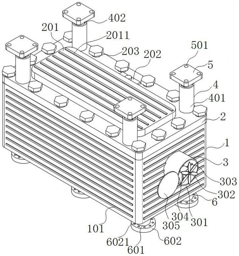
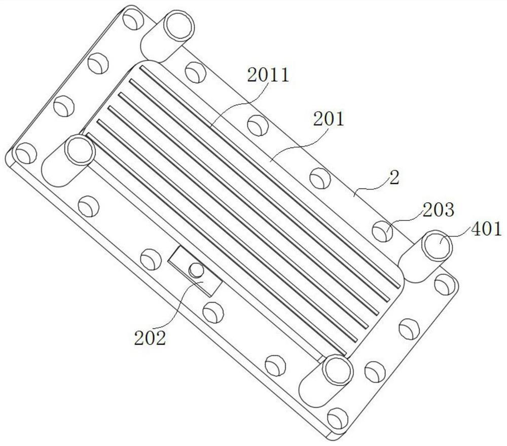
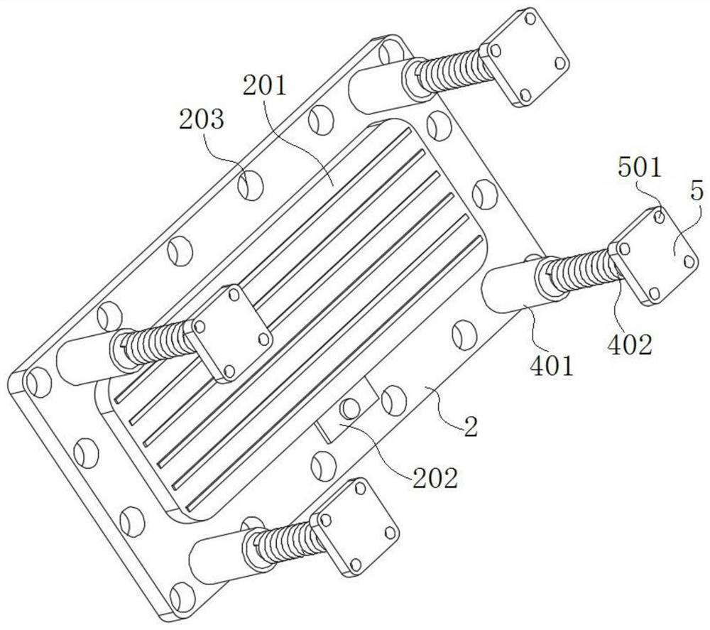
[0004] The purpose of the present invention is to provide a high-strength explosion-proof and shock-proof battery for new energy vehicles. By designing a coverless battery, the surrounding side is covered with reinforcing ribs, a pull-out battery module fixing frame is installed inside, and pipe-type battery modules are installed on both sides. The battery box structure of the heat dissipation device is isolated and fixed between the battery modules by fire-proof and heat-insulating panels. The bottom is equipped with an elastic elastic buffer support device, which solves the problems of poor anti-knock performance, unreasonable heat dissipation structure and unstable battery fixing of existing new energy vehicle batteries.

Method used


Image

  • A high-strength explosion-proof and shock-proof battery for new energy vehicles
  • A high-strength explosion-proof and shock-proof battery for new energy vehicles
  • A high-strength explosion-proof and shock-proof battery for new energy vehicles

Examples


Embodiment Construction

[0035]The following will clearly and completely describe the technical solutions in the embodiments of the present invention with reference to the accompanying drawings in the embodiments of the present invention. Obviously, the described embodiments are only some, not all, embodiments of the present invention. Based on the embodiments of the present invention, all other embodiments obtained by persons of ordinary skill in the art without creative efforts fall within the protection scope of the present invention.

[0036] In the description of the present invention, it should be understood that the terms "top", "bottom", "inner", "bottom", "inner wall", "side", "surface", etc. indicate orientation or positional relationship, and are only for the purpose of It is convenient to describe the present invention and simplify the description, but does not indicate or imply that the components or elements referred to must have a specific orientation, be constructed and operate in a spe...


PUM


Abstract

The invention discloses a high-strength explosion-proof shockproof battery for new energy vehicles, and relates to the field of new energy vehicle batteries. The invention includes a battery box; the top of the battery box is equipped with a box cover, the bottom of the battery box is provided with a number of elastic support devices, two opposite sides of the battery box are each equipped with a pipeline type cooling device, and the inner bottom of the battery box is installed with a battery module. The frame is fixed, and several elastic buffer devices are installed on one surface of the case cover. The present invention designs a battery box structure without a cover, the surrounding side is covered with reinforcing ribs, a pull-out battery module fixing frame is installed inside, and a pipe-type heat dissipation device is installed on both sides, and a matching battery box is installed on the top of the battery box. The box cover with elastic buffer device and fiber cement explosion-proof plate is installed with elastic buffer support device at the bottom of the battery box, which improves the anti-explosion performance of the new energy vehicle battery, the heat dissipation structure and the stability of battery fixing.

Description

technical field [0001] The invention belongs to the field of new energy vehicle batteries, in particular to a high-strength explosion-proof and shockproof battery for new energy vehicles. Background technique [0002] New energy vehicles refer to the use of unconventional vehicle fuels as power sources (or the use of conventional vehicle fuels, the use of new vehicle power devices), integrated vehicle power control and advanced technology in driving, the formation of advanced technical principles, with Automobiles with new technologies and new structures, among which new energy vehicles powered by electricity are the most mature. [0003] With the continuous development of electric new energy vehicles at this stage, more and more battery packs equipped in electric new energy vehicles can meet the needs of the market, but there are still great potential safety hazards for their safety issues. The battery of electric new energy vehicles is only protected by the PCB protection...

Claims


Application Information

Patent Timeline
Patent Type & Authority Patents(China)
IPC IPC(8): H01M50/209H01M50/204H01M10/655H01M10/613H01M10/6563H01M10/658H01M50/20H01M50/24
CPCH01M10/655H01M50/20H01M50/24Y02E60/10
Inventor 陈伟陈双龙
Owner 安徽上造智能设备科技有限公司
Why Eureka
Try Eureka