
Novel lift counterweight device

A new type of elevator technology, applied in transportation and packaging, elevators, lifting equipment in mines, etc., can solve problems such as poor shock absorption performance, and achieve good shock absorption performance, good buffering effect, and high safety performance.

Inactive Publication Date: 2018-09-28
湖州德玛吉电梯有限公司
View PDF6 Cites 1 Cited by
  • Summary
  • Abstract
  • Description
  • Claims
  • Application Information

AI Technical Summary

Problems solved by technology

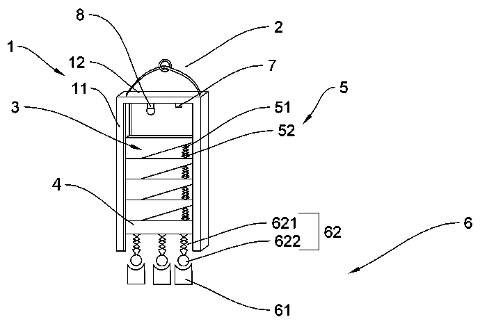
[0006] In order to solve the technical defect of the poor shock absorption performance of the counterweight device in the prior art, the present invention proposes a new type of elevator counterweight device, which includes a frame and a rope connector arranged on the frame, and the frame includes two sides arranged in parallel wall, the fixed beam connecting the two side walls, the side wall is provided with a chute, the cross section of the chute is cross-shaped; the two ends are provided with sliding counterweights of limit brackets, and the limit brackets are respectively accommodated In the chute, the sliding counterweight can slide up and down in the chute, the lower end of the sliding counterweight is provided with a first buffer; the magnetic buffer includes a fixed part with a magnetic attraction, a The elastic part of the magnetic attraction, the fixed part has a concave surface capable of accommodating the elastic part; it also includes an acceleration sensor for detecting the motion state of the sliding counterweight

Method used


Image

  • Novel lift counterweight device
  • Novel lift counterweight device
  • Novel lift counterweight device

Examples


Embodiment Construction

[0020] The present invention will be described in detail below in conjunction with specific embodiments.

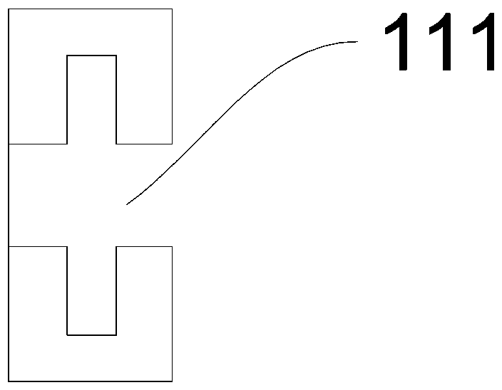
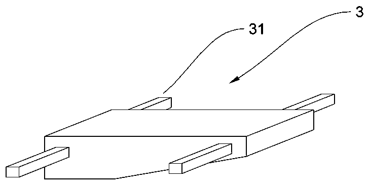
[0021] see Figure 1 to Figure 3 , a new elevator counterweight device, comprising a frame 1, a rope connector 2 arranged on the frame 1, the frame 1 includes two side walls 11 arranged in parallel, and a fixed beam 12 connecting the two side walls 11, the A chute 111 is provided on the side wall 11, and the cross-section of the chute 111 is cross-shaped; sliding counterweights 3 with limit brackets 31 are provided at both ends, and the limit brackets 31 are respectively accommodated in the chute 111 , so that the sliding counterweight 3 can slide up and down in the chute 111, the lower end of the sliding counterweight 3 is provided with a first buffer 5; the magnetic buffer 6 includes a fixed part 61 with a magnetic attraction 1. An elastic part 62 with a magnetic attraction, the fixed part 61 has a concave surface capable of accommodating the elastic part 62; it also i...


PUM


Abstract

The invention provides a novel lift counterweight device and belongs to the technical field of lifts. The novel lift counterweight device comprises a frame, a rope connecting part arranged on the frame, a sliding counterweight block with the two ends being provided with limiting supports, and a magnetic buffer part, and further comprises an acceleration sensor, wherein the frame comprises two sidewalls arranged in parallel, and a fixing beam connected with the two side walls; sliding chutes are arranged on the side walls; the cross section of the sliding chutes is in a cross shape; the limiting supports are contained in the sliding chutes correspondingly; first buffer parts are arranged at the lower end of the sliding counterweight block; the magnetic buffer part comprises a fixing part and an elastic part; and the fixing part is provided with a concave surface capable of containing the elastic part. By arranging the cross section of the sliding chutes in the cross shape, the effect that the sliding counterweight block is not deviated from a track during downward sliding is ensured, impact force caused by sudden weightlessness can be decomposed by the multiple first buffer parts,the good buffer effect is achieved, the novel lift counterweight device is good in damping performance, and the safety performance of a lift during accidents is high.

Description

technical field [0001] The invention relates to the technical field of elevators, in particular to a novel elevator counterweight device. Background technique [0002] Generally, elevators use counterweights. Modern elevators are mainly composed of traction machines (winches), guide rails, counterweight devices, safety devices (such as speed governors, safety gears and buffers, etc.), signal control systems, cars and hall doors. However, the general hydraulic elevator does not have a counterweight device. [0003] In the elevators currently in use, the counterweight device is an indispensable part of the traction elevator. By balancing the weight of the car and part of the weight of the elevator load, the loss of motor power is reduced. [0004] The counterweight device of an ordinary elevator includes two upper side beams, two vertical beams, two lower side beams, a counterweight iron platen and a counterweight iron. The two vertical beams are parallel to each other. Th...

Claims


Application Information

Patent Timeline
IPC IPC(8): B66B17/12B66B5/00
CPCB66B5/0031B66B17/12
Inventor 杨荣根王建伟饶树刚
Owner 湖州德玛吉电梯有限公司
Learn More