
Automatic drawing-off auxiliary detection device for yarns

A technology of auxiliary detection and thread pressing device, which is applied in the field of yarn textile machinery, and can solve the problems that cannot meet the needs of automatic production and use

Inactive Publication Date: 2018-09-28
佛山市南海畯腾染织有限公司
View PDF1 Cites 0 Cited by
  • Summary
  • Abstract
  • Description
  • Claims
  • Application Information

AI Technical Summary

Problems solved by technology

This invention cannot realize the clamping or re-tensioning of the yarn according to the state of yarn breakage or shedding, and cannot meet the requirements of automatic production

Method used


Image

  • Automatic drawing-off auxiliary detection device for yarns
  • Automatic drawing-off auxiliary detection device for yarns
  • Automatic drawing-off auxiliary detection device for yarns

Examples


specific Embodiment approach 1

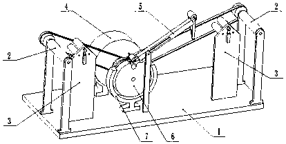
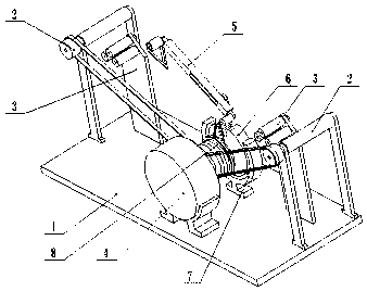
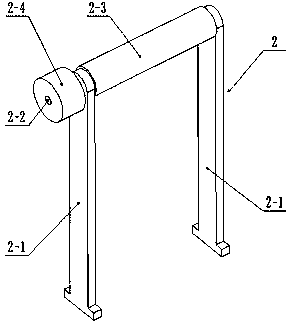
[0035] Such as Figure 1-17As shown, a yarn automatic extraction auxiliary detection device includes a frame 1, a thread feeding roller 2, a thread pressing device 3, a driving device 4, a tensioning device 5, a connecting rod sheave 6, a sheave frame 7 and Clutch device 8, each of the left and right ends of the frame 1 is fixedly connected with a transmission line rotating roller 2, and each of the left and right ends of the frame 1 is fixedly connected with a crimping device 3, and the two crimping devices 3 are located at two On the inner side of the line transmission roller 2, the tensioning device 5 is arranged at the middle end of the frame 1, the driving device 4 is fixedly connected to the frame 1, and the connecting rod sheave 6 is clearance-fitted on the sheave frame 7 Above, the sheave frame 7 is fixedly connected to the frame 1, the connecting rod sheave 6 is fixedly connected to one end of the clutch device 8, and the other end of the clutch device 8 is fixedly co...


PUM


Abstract

The invention relates to the technical field of yarn textile machinery, in particular to an automatic drawing-off auxiliary detection device for yarns. The automatic yarn drawing-off auxiliary detection device comprises a machine frame, wire conveying rollers, wire pressing devices, a driving device, a tensioning device, a connecting rod groove wheel, a groove wheel frame and a clutch device, wherein the left end and the right end of the machine frame are fixedly connected with the wire conveying rollers respectively, the left end and the right end of the machine frame are fixedly connected with the wire pressing devices respectively, the two wire pressing devices are located on the inner sides of the two wire conveying rollers, the tensioning device is arranged at the middle end of the machine frame, the driving device is fixedly connected to the machine frame, the connecting rod groove wheel is in clearance fit with the groove wheel frame, the groove wheel frame is fixedly connectedto the machine frame, the connecting rod groove wheel is fixedly connected to one end of the clutch device, and the other end of the clutch device is fixedly connected with the driving device. According to the automatic drawing-off auxiliary detection device, automatic take-up tensioning can be realized when the yarns are separated, the yarn pressing devices can achieve clamping and fixing the yarns when the yarns break or fall off from the tensioning device, and the yarns are prevented from being drawn off.

Description

technical field [0001] The invention relates to the technical field of yarn textile machinery, in particular to an auxiliary detection device for automatic yarn extraction. Background technique [0002] The existing patent application number is a yarn tensioner (T) of CN201110034641.5, the yarn tensioner includes a series of rigid yarn deflection elements (1), and these yarn deflection elements jointly determine the yarn path (P), the yarn deflecting elements are spaced apart in the middle on opposite sides of the yarn path, so that a corresponding yarn deflecting element is arranged on one side and makes it relative to the yarn arranged on the opposite side The deflection elements (1) are offset in the direction of yarn travel (D), at least one of the yarn deflection elements (2a, 2b) can be adjusted substantially perpendicular to the To change the tensioning effect, the yarn path (P) consists of at least one thin-walled flexible spring leaf (8a, 8b) on each side of the ya...

Claims


Application Information

Patent Timeline
IPC IPC(8): B65H59/18
CPCB65H59/18B65H2701/31
Inventor 冼宽礼
Owner 佛山市南海畯腾染织有限公司
Learn More