Trimmer

A trimmer and fuselage technology, applied in the field of hair trimming equipment manufacturing, can solve problems such as enhanced processing and assembly precision requirements, product launch, and difficult trimming, so as to reduce processing and assembly precision requirements, improve design aesthetics, and reduce design The effect of modeling

Pending Publication Date: 2018-09-28
WENZHOU RIDIAN ELECTRICAL APPLIANCE
View PDF0 Cites 0 Cited by
  • Summary
  • Abstract
  • Description
  • Claims
  • Application Information

AI Technical Summary

Problems solved by technology

[0003] At present, the following problems are found in the use of existing trimmers: 1. After the cutter head is installed on the handle, the output end of the motor is directly connected through the movable blade, so that the rotary drive of the motor can be converted into the reciprocating motion of the movable blade. Sliding, so that the cutting hair of the cutter head is realized
However, during the installation process of the cutter head, the eccentric wheel on the output end of the motor needs to be installed in cooperation with the conversion piece on the movable blade, so the installation of the cutter head requires high assembly accuracy requirements, which limits the installation structure of the motor and the movable blade. The requirements for processing and assembly precision are enhanced, and at the same time, due to the limitation of installation space, it is not conducive to the design of the shell, which is not conducive to improving the design aesthetics of the trimmer
[0004] 2. Even if you adjust the swing direction of the trimmer, there will be areas that are difficult to trim, such as behind the ears or the nape of the neck
This action is inconvenient and often causes discomfort to the user's wrist or hand after continuous use, and reduces the precision and / or efficiency of the trimmer since the blades are not fully in contact with the trimmed area
For this reason, many manufacturers and people of insight have developed and developed, but so far no ideal products have come out.

Method used


Image

  • Trimmer
  • Trimmer
  • Trimmer

Examples


Embodiment Construction

[0030] The present invention will be described in further detail below in conjunction with the accompanying drawings and embodiments. Wherein the same components are denoted by the same reference numerals. It should be noted that the words "front", "rear", "left", "right", "upper" and "lower" used in the following description refer to the directions in the drawings, and the words "bottom" and "top "Face", "inner" and "outer" refer to directions toward or away from, respectively, the geometric center of a particular component.

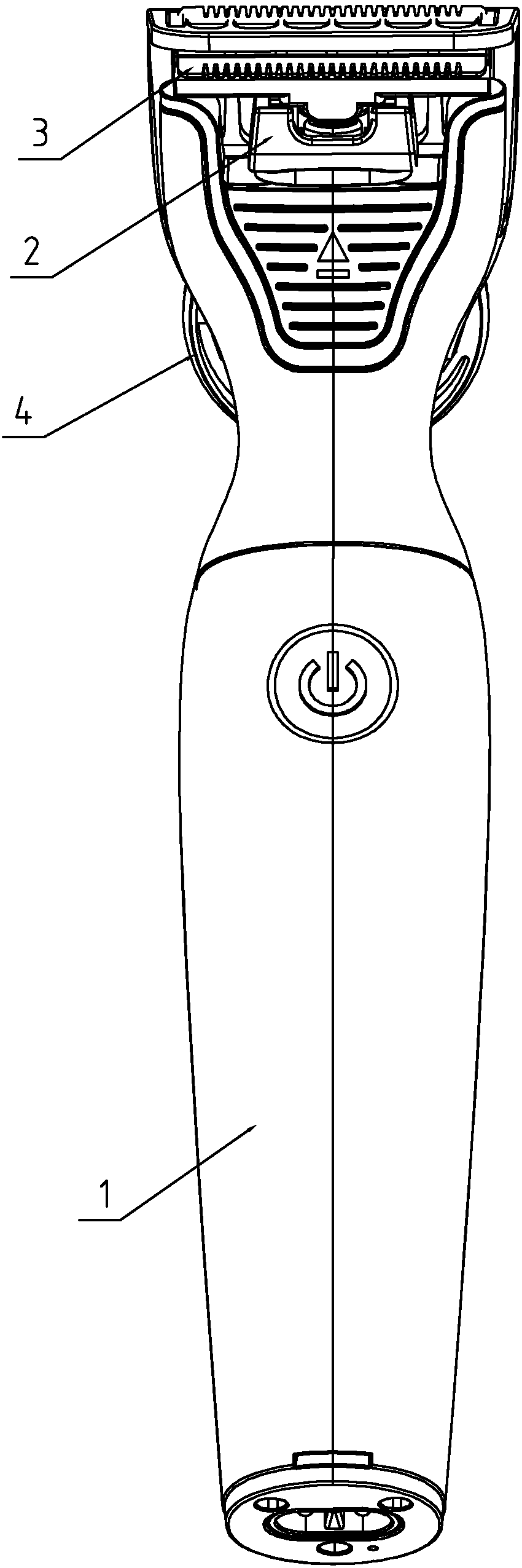
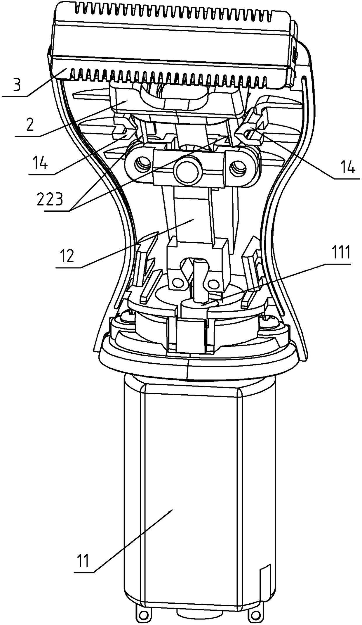
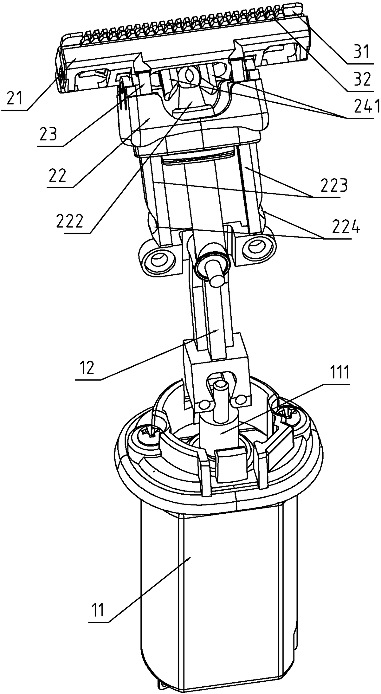
[0031] refer to Figure 1-12 As shown, a trimmer includes a fuselage 1, a motor 11 embedded in the fuselage 1, a cutter head assembly 2 installed on the head of the fuselage 1, a blade assembly 3 installed on the cutter head assembly 2, The blade assembly 3 includes a fixed blade 31 and a movable blade 32, both sides of the fixed blade 31 and the movable blade 32 in the length direction are provided with cutter teeth, and the cutter head assembly 2 in...


PUM


Abstract

The invention discloses a trimmer. According to the technical scheme, the trimmer is mainly characterized by comprising a machine body, a motor, a tool bit assembly and a blade assembly. The tool bitassembly comprises a tool bit bracket and an installation seat, wherein the tool bit bracket and the installation seat are connected in a hinged manner. The installation seat is provided with an elastic assembly capable of pushing the tool bit bracket to rotate, and the elastic assembly is located on one side of the tool bit bracket in the width direction and can push the tool bit bracket to rotate around a hinge shaft of the installation seat towards the other side. The output end of the motor is provided with a transmission arm, the transmission arm comprises a hinge block, an upper arm anda lower arm. The length directions of the upper arm and the lower arm and the length direction of the hinge block are all inclined. When the motor drives an eccentric wheel to rotate, the motor can drive the transmission arm to swing around the hinged position with the machine body by pushing a butt-joint piece, and a movable blade is driven to perform cutting swing through reciprocating swing ofthe transmission arm and meanwhile through pushing of butt-joint pushing pieces on the two sides of the upper arm. By means of the connection structure of the trimmer, the machining and assembling precision can be lowered, and the trimming direction can be adjusted through a tool bit.

Description

technical field [0001] The invention relates to the technical field of hair clipping equipment manufacturing, more specifically, it relates to a trimmer. Background technique [0002] Electric hair trimmers or barber clippers are generally used by stylists, barbers or individuals to style hair and typically include a handle and a blade portion connected to the handle, wherein the handle has a housing containing an electric motor, in order to receive the electric motor The driving force of the knife head part is usually mounted on the handle. The blade set in the blade assembly includes a fixed blade and a movable movable blade. The movable blade is roughly parallel to the fixed blade and reciprocates in the lateral direction to form a cutting similar to scissors. sports. [0003] At present, the following problems are found in the use of existing trimmers: 1. After the cutter head is installed on the handle, the output end of the motor is directly connected through the mova...

Claims


Application Information

Patent Timeline
IPC IPC(8): B26B19/20B26B19/08B26B19/28B26B19/38
CPCB26B19/08B26B19/20B26B19/28B26B19/3813B26B19/3826
Inventor 张弛
Owner WENZHOU RIDIAN ELECTRICAL APPLIANCE
Why Eureka
Try Eureka