
Packaging machine capable of rapidly switching specifications

A technology for fast switching and packaging machines, which is applied in the directions of packaging, transportation and packaging, and the type of packaged items. It can solve the problems of time-consuming adjustment, poor accuracy, and inconvenient adjustment, and achieve shortened travel distance, low processing and assembly accuracy requirements, and saving The effect of rise and fall times

Pending Publication Date: 2021-09-07
KEDA INDUSTRIAL GROUP CO LTD
View PDF0 Cites 2 Cited by
  • Summary
  • Abstract
  • Description
  • Claims
  • Application Information

AI Technical Summary

Problems solved by technology

The other group of hemming parts on the opposite side is limited by space, and the length can only be less than the length of the carton in production, so as to avoid interference with the other group of hemming parts. In this way, in order to adapt to different specifications and ensure a good hemming effect, often The method used is to shorten the length of the other set of hemming pieces on the opposite side, and use multiple sets of hemming pieces to hem at the same time. When it is necessary to switch specifications, manually adjust the spacing of the multiple sets of hemming pieces and increase or decrease the hemming appropriately. In order to achieve a better hemming effect, but the hemming mechanism is generally in the middle of the conveyor belt, it is inconvenient to adjust, and the accuracy of manual adjustment is poor, and the adjustment is more time-consuming

Method used


Image

  • Packaging machine capable of rapidly switching specifications
  • Packaging machine capable of rapidly switching specifications
  • Packaging machine capable of rapidly switching specifications

Examples


Embodiment 1

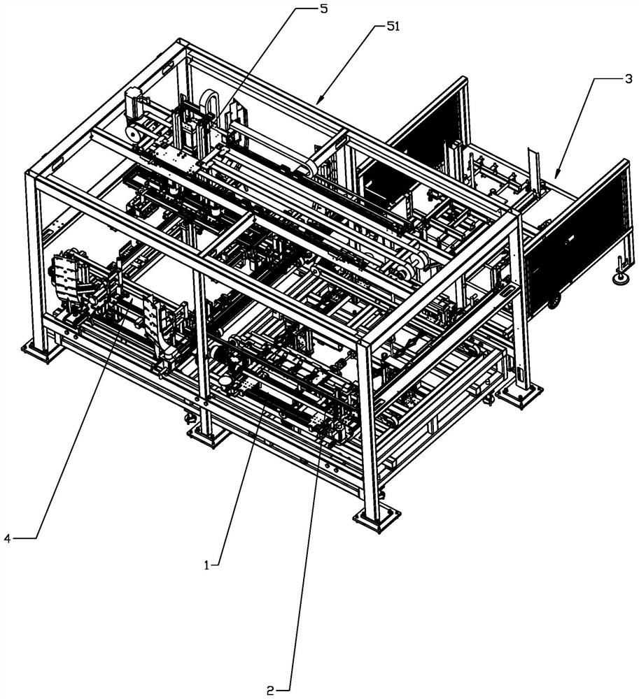
[0052] Such as figure 1 , 2 , 6, 12, 21, and 25, a packaging machine for quickly switching specifications, including a shaping and setting device 1, a brick holding device 2, a forming device 3, a paper bin device 4 and a paper feeding device 5, the The shaping and angle setting device is arranged on the front half of the packaging machine frame, and the shaping and angle setting device 4 includes a corner-taking mobile frame, a brick feeding mechanism arranged on the corner-taking mobile frame, left and right clapping components, front and rear clapping All components; the brick-holding angle device is installed above the shaping and angle-setting device through the brick-moving frame 51, and the brick-holding angle device includes a brick-holding angle lifting mechanism arranged on the brick-moving frame 51, The translation mechanism 53 arranged on the brick-moving frame 51, the brick-holding clamp mechanism 54 provided below the brick-holding angle lifting mechanism 52, th...


PUM


Abstract

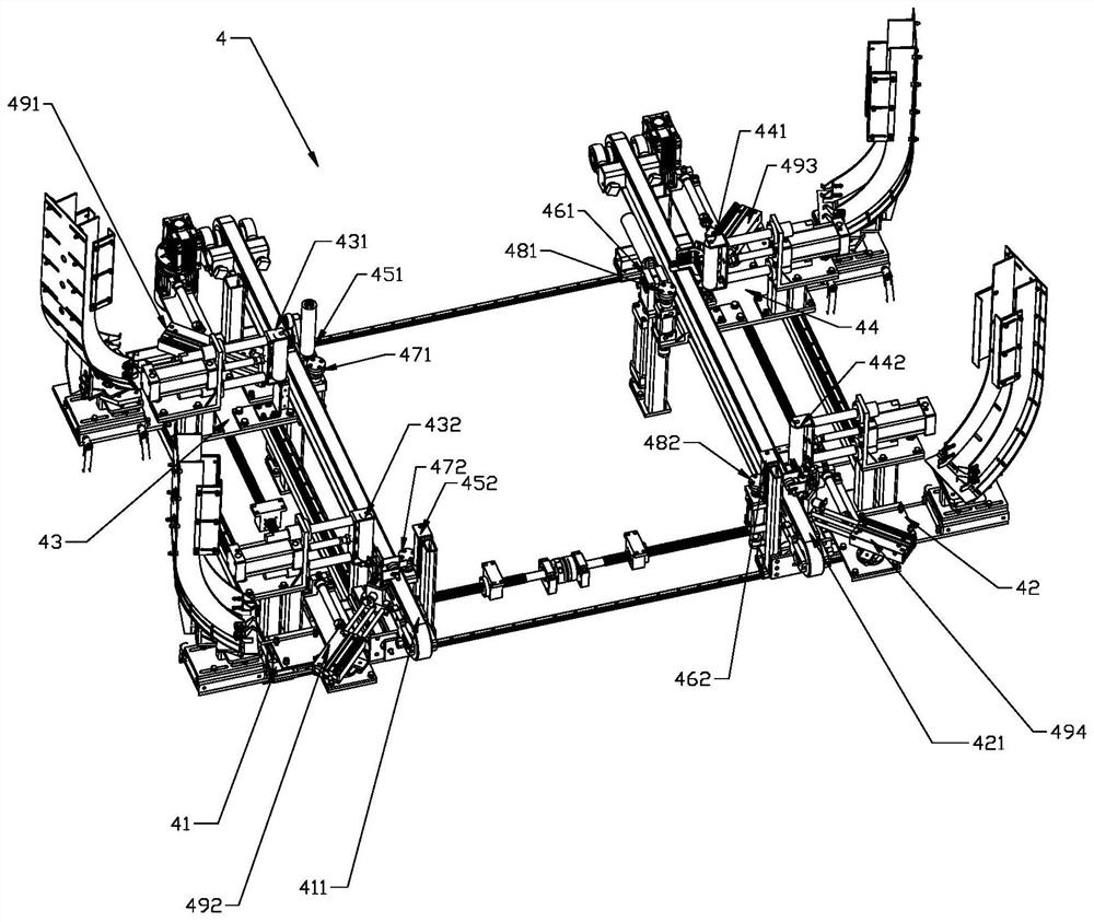
The invention discloses a packaging machine capable of quickly switching specifications. The packaging machine comprises a shaping and corner placing device, a brick and corner holding device, a forming device, a paper bin device and a paper taking and feeding device, and the shaping and corner placing device is arranged at the front end of a packaging machine rack; the brick and corner holding device is mounted above the shaping and corner placing device through a brick moving rack; the forming device is arranged on the rear end side of the shaping and corner placing device. the paper bin device is arranged on one side of the forming device; the paper taking and feeding device is arranged above the forming device; and the paper taking and feeding device clamps the cartons in the paper bin device and then places the cartons in the forming device. The shaping and corner placing device reduces the adjusting complexity and saves the cost of an adjusting mechanism, a brick-holding corner-holding lifting mechanism is driven by double lifting cylinders in series connection, the lifting stroke of the brick-holding corner-holding device is increased, and the lifting time is saved. The forming device can automatically adjust the edge folding distances of the front side edge, the rear side edge, the left side edge and the right side edge of a carton in the ceramic tile packaging process so as to adapt to cartons and ceramic tile stacks of different sizes.

Description

technical field [0001] The invention belongs to the field of packaging equipment, and in particular relates to a packaging machine for quickly switching specifications. Background technique [0002] China's ceramic industry has been developing rapidly for many years. The market competition is becoming increasingly fierce, and corporate profits are declining year by year. Controlling and reducing costs or improving the efficiency of automation equipment has become the choice of more and more companies to enhance their competitiveness. In this case, the measures taken by enterprises are to improve competitiveness by controlling and reducing costs, so improving the production efficiency of automation equipment becomes the key to determining whether enterprises can win the competition. In the production process of ceramic automation equipment, the high-speed and effective operation of each link determines the level of production efficiency. There are many types of ceramic tiles...

Claims


Application Information

Patent Timeline
IPC IPC(8): B65B59/00B65B23/20B65B43/24B65B43/26B65B43/18B65B61/20
CPCB65B59/001B65B23/20B65B43/24B65B43/265B65B43/185B65B61/20
Inventor 张立胡嘉祺吉仲政林风梁永盛
Owner KEDA INDUSTRIAL GROUP CO LTD
Learn More