
Compressor rotor large nut assembling support

A technology for compressor rotors and assembling brackets, which is applied to hand-held tools, manufacturing tools, etc., can solve problems such as exceeding the manual operation ability of workshop operators, inability to complete rotor assembly work, and difficulty in assembling large nuts. The effect of improving the technical level of tools and improving labor efficiency

Active Publication Date: 2018-09-28
SHENYANG TURBO MASCH CORP
View PDF13 Cites 0 Cited by
  • Summary
  • Abstract
  • Description
  • Claims
  • Application Information

AI Technical Summary

Problems solved by technology

The large nut is mounted horizontally, and the weight of the large nut is too large for the manual operation of the workshop operator. Moreover, there is no hoisting position in the direction of the outer circumference of the large nut, which makes the assembly of the large nut difficult. If the large nut is not assembled on the main shaft , the assembly work of the rotor cannot be completed

Method used


Image

  • Compressor rotor large nut assembling support
  • Compressor rotor large nut assembling support
  • Compressor rotor large nut assembling support

Examples


Embodiment Construction

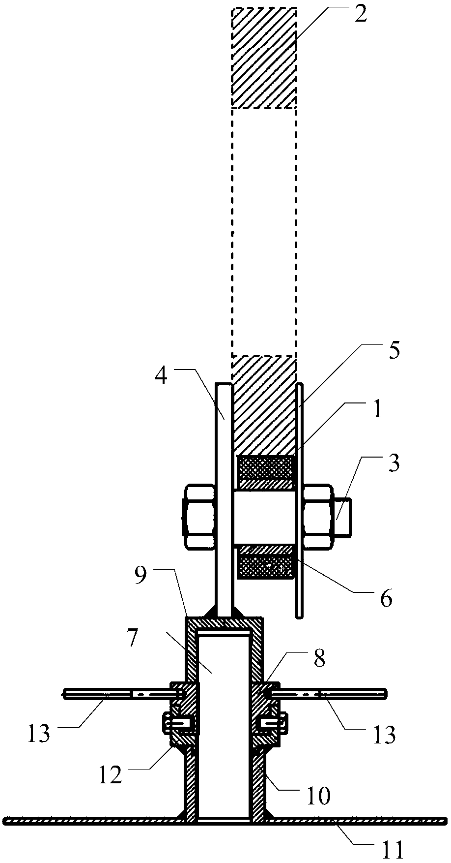
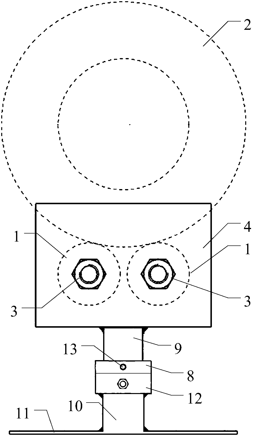
[0032] The specific implementation of the compressor rotor big nut assembly bracket of the present invention will be described below with reference to the accompanying drawings.

[0033] Embodiment of assembly bracket of compressor rotor big nut

[0034] Such as figure 1 As shown, the structure diagram of the compressor rotor according to the present invention, the compressor rotor includes a main shaft 100 , and an impeller 200 and a large nut 2 respectively installed on the main shaft 100 .

[0035] Such as figure 2 , image 3 As shown, the compressor rotor big nut assembly bracket described in this embodiment includes a supporting part, a supporting part, and a lifting part, wherein: the supporting part is used to limit the position of the big nut; the supporting part is connected to the supporting part in rotation ; The supporting part is fixedly connected with the lifting part; the lifting part is a threaded screw lifting mechanism.

[0036] The rotating part include...


PUM


Abstract

The invention discloses a compressor rotor large nut assembling support. The support comprises a pop-jump part, a supporting part and a lifting part; the pop-jump part is used for limiting a large nut, the pop-jump part and the supporting part are rotatably connected, the supporting part is fixedly connected with the lifting part, and the lifting part is a thread and screw rod lifting mechanism. According to the compressor rotor large nut assembling support, free rotation of a large nut and moving within a certain range can be achieved, mounting work of a superheavy large nut is achieved, andlabor efficiency is improved.

Description

technical field [0001] The invention relates to an auxiliary device for assembling a compressor rotor, in particular to an assembly bracket for a large nut of a compressor rotor. Background technique [0002] The rotor at the compressor end is mainly composed of main shaft, impeller, spacer, thrust disc, large nut and other parts. The assembly process of the main shaft is to erect the main shaft, make the main shaft perpendicular to the operating platform, fix the main shaft, use the crane to lift the impeller and wait for the parts to be installed, and then drop it vertically. After the assembly of the impeller, the spacer and the main shaft is completed, install the big nut and other parts. The large nut is mounted horizontally, and the weight of the large nut is too large for the manual operation of the workshop operator. Moreover, there is no hoisting position in the direction of the outer circumference of the large nut, which makes the assembly of the large nut difficu...

Claims


Application Information

Patent Timeline
Patent Type & Authority Applications(China)
IPC IPC(8): B25B27/14
CPCB25B27/14
Inventor 王宝华周顺新刘铎金锐赵德金于洋关欣张艳梅
Owner SHENYANG TURBO MASCH CORP
Learn More