Energy enhancement optimization method for marking edge of laser equipment
A technology of laser equipment and optimization method, which is applied in the direction of laser welding equipment, welding equipment, metal processing equipment, etc., can solve problems such as failure to meet process standards, laser marking, etc., and achieve better marking effect
- Summary
- Abstract
- Description
- Claims
- Application Information
AI Technical Summary
Problems solved by technology
Method used
Image

Examples
Embodiment 1
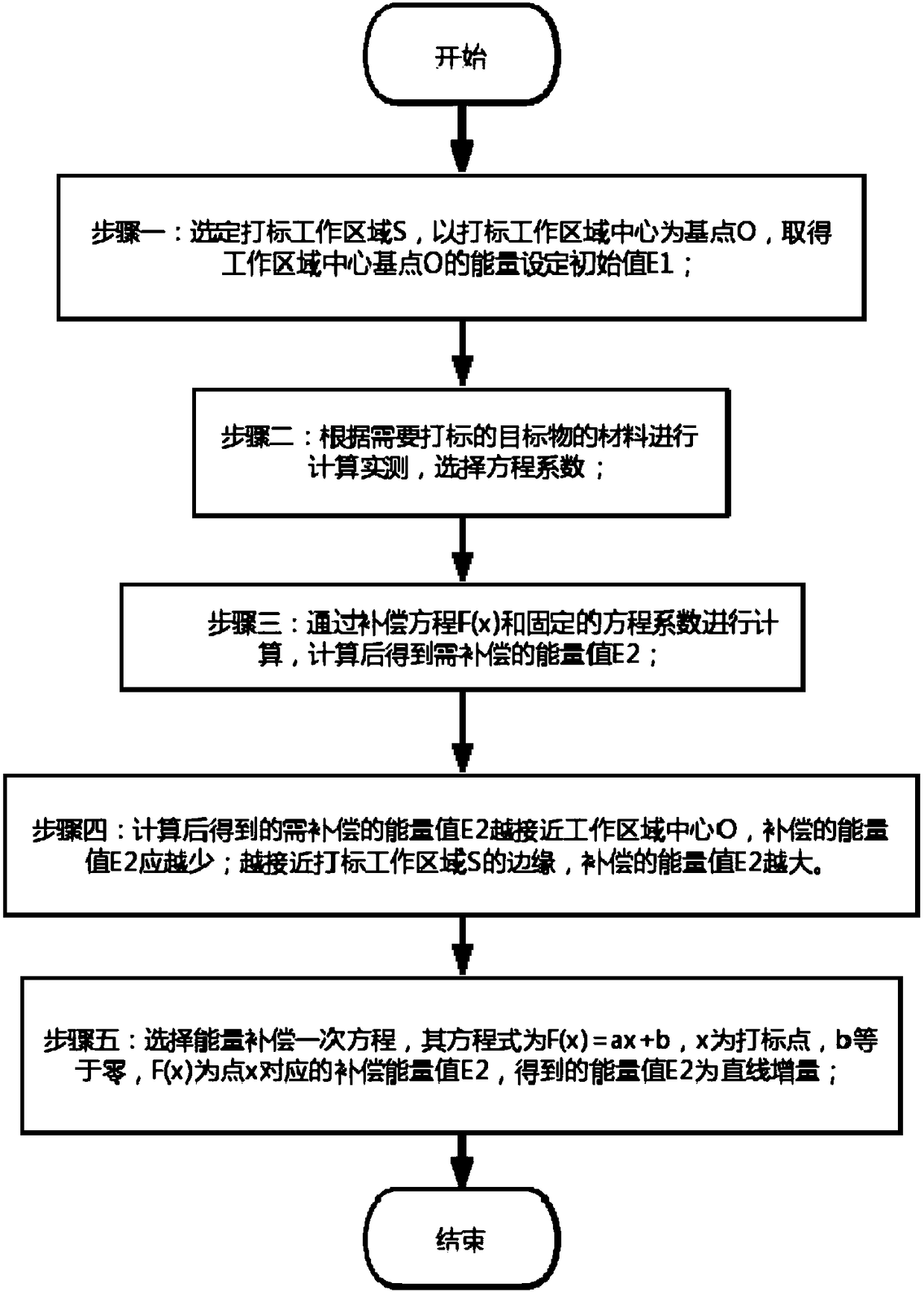
[0032] An energy enhancement optimization method for marking edges of laser equipment, comprising:
[0033] Step 1: Select the marking work area S, take the center of the marking work area as the base point O, and obtain the energy setting initial value E1 of the base point O of the work area center;
[0034] Step 2: Calculate and measure according to the material of the target object to be marked, and select the coefficient of the equation;
[0035] Step 3: Calculate through the compensation equation F(x) and the selected equation coefficients, and obtain the energy value E2 to be compensated after calculation;
[0036] Step 4: The closer the calculated energy value E2 to be compensated is to the center O of the working area, the smaller the compensated energy value E2 should be; the closer to the edge of the marking working area S, the larger the compensated energy value E2 should be.
[0037] as attached figure 1 and 2 As shown, the present embodiment 1 adopts the energy...
Embodiment 2
[0045] An energy enhancement optimization method for marking edges of laser equipment, comprising:
[0046] Step 1: Select the marking work area S, take the center of the marking work area as the base point O, and obtain the energy setting initial value E1 of the base point O of the work area center;
[0047]Step 2: Calculate and measure according to the material of the target object to be marked, and select the coefficient of the equation;
[0048] Step 3: Calculate through the compensation equation F(x) and the selected equation coefficients, and obtain the energy value E2 to be compensated after calculation;
[0049] Step 4: The closer the calculated energy value E2 to be compensated is to the center O of the working area, the smaller the compensated energy value E2 should be; the closer to the edge of the marking working area S, the larger the compensated energy value E2 should be.
[0050] as attached Figure 5 and 6 As shown, the present embodiment 2 adopts the energy...
Embodiment 3
[0054] An energy enhancement optimization method for marking edges of laser equipment, comprising:
[0055] Step 1: Select the marking work area S, take the center of the marking work area as the base point O, and obtain the energy setting initial value E1 of the base point O of the work area center;
[0056] Step 2: Calculate and measure according to the material of the target object to be marked, and select the coefficient of the equation;
[0057] Step 3: Calculate through the compensation equation F(x) and the selected equation coefficients, and obtain the energy value E2 to be compensated after calculation;
[0058] Step 4: The closer the calculated energy value E2 to be compensated is to the center O of the working area, the smaller the compensated energy value E2 should be; the closer to the edge of the marking working area S, the larger the compensated energy value E2 should be.
[0059] as attached Figure 7 and 8 As shown, the present embodiment 3 adopts the energ...
PUM
 Abstract
Description
Claims
Application Information
 - R&D
- Intellectual Property
- Life Sciences
- Materials
- Tech Scout
- Unparalleled Data Quality
- Higher Quality Content
- 60% Fewer Hallucinations
Browse by: Latest US Patents, China's latest patents, Technical Efficacy Thesaurus, Application Domain, Technology Topic, Popular Technical Reports.
© 2025 PatSnap. All rights reserved.Legal|Privacy policy|Modern Slavery Act Transparency Statement|Sitemap|About US| Contact US: help@patsnap.com