USB interface charging circuit

A USB interface and charging circuit technology, applied in the electronic field, can solve the problems of not meeting the certification rules, deviation of sampling resistance, deviation of output voltage, etc.

Inactive Publication Date: 2018-09-25
FAURECIA CLARION ELECTRONICS (XIAMEN) CO LTD
View PDF0 Cites 7 Cited by
  • Summary
  • Abstract
  • Description
  • Claims
  • Application Information

AI Technical Summary

Problems solved by technology

In addition, because the sampling resistor of the USB power supply has a deviation, the output voltage also has a deviation, and the output voltage setting is close to the specification limit value. If the output voltage is slightly higher, i

Method used


Image

  • USB interface charging circuit
  • USB interface charging circuit

Examples


Embodiment Construction

[0023] The following will clearly and completely describe the technical solutions in the embodiments of the present invention with reference to the accompanying drawings in the embodiments of the present invention. Obviously, the described embodiments are only some, not all, embodiments of the present invention. Based on the embodiments of the present invention, all other embodiments obtained by persons of ordinary skill in the art without making creative efforts belong to the protection scope of the present invention.

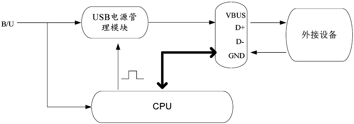
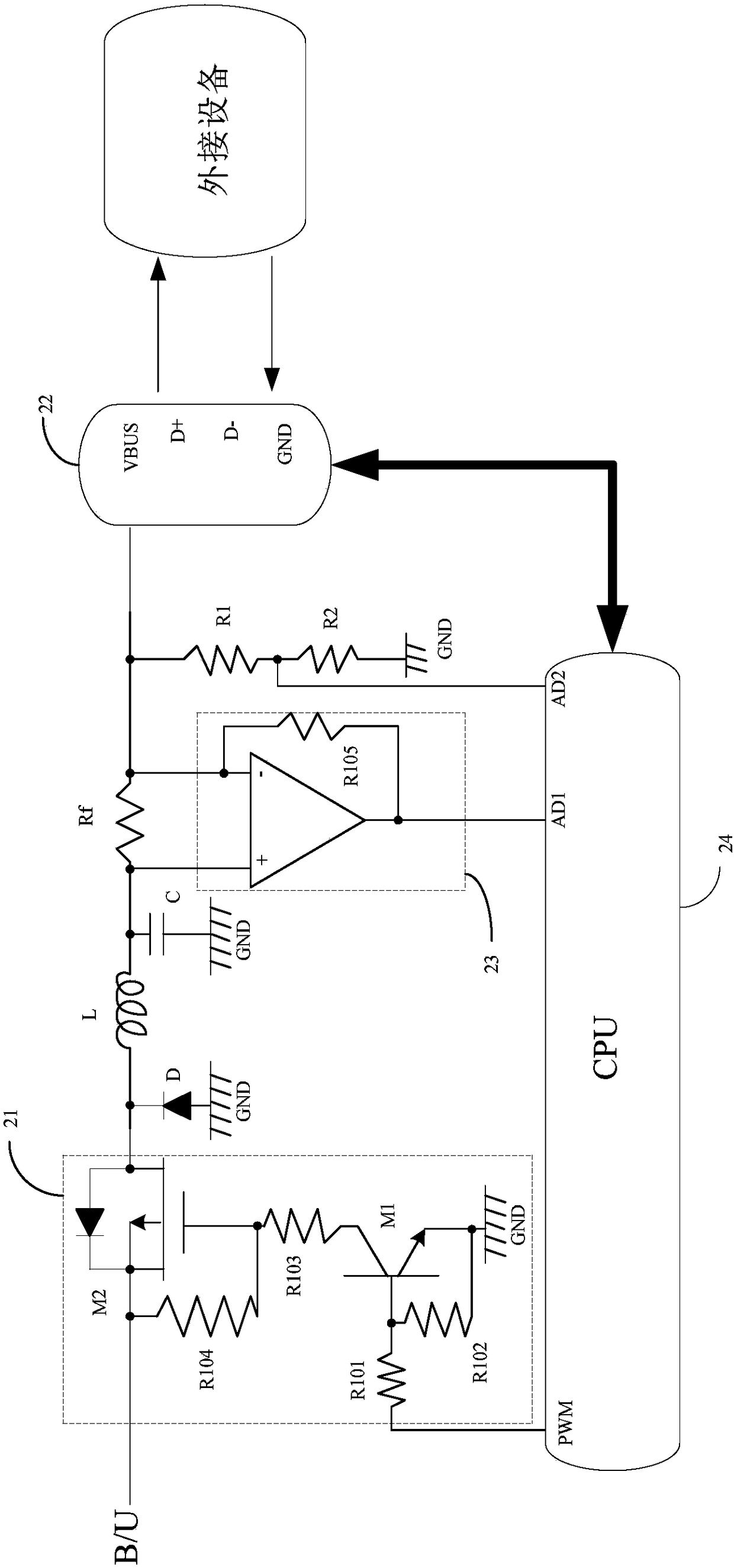
[0024] refer to figure 2 , the embodiment of the present invention provides a USB interface charging circuit, comprising:

[0025] The voltage dividing resistor Rf, the first end of the voltage dividing resistor Rf is connected to the power supply input terminal B / U through the PWM voltage modulation module 21, the second end of the voltage dividing resistor Rf is connected to the power supply pin VBUS of the USB interface 22, and the charging provided by the...


PUM


Abstract

Embodiments of the invention provide a USB interface charging circuit, and relates to auto parts. The circuit can compensate for charging voltages according to USB line losses so that the voltage dropcaused by the line losses can be compensated for, and thus, the USB charging voltages can accord with related certification rules. The circuit includes a voltage dividing resistor, a voltage detection unit, a CPU and a PWM voltage modulation module; the control end of the PWM voltage modulation module is connected to the PWM end of the CPU; the input end of the PWM voltage modulation module is connected to the input end of a power supply; the output end of the PWM voltage modulation module is connected to the first end of the voltage dividing resistor; and the PWM voltage modulation module isused for receiving a PWM control signal, and adjusts the duty ratio of the conducting time of the input end and output end of the PWM voltage modulation module according to the PWM control signal soas to adjust the voltages output by the power supply pins of a USB interface. The embodiment of the invention is used for the USB interfaces.

Description

technical field [0001] Embodiments of the present invention relate to the field of electronic technology, in particular to a USB interface charging circuit. Background technique [0002] In recent years, in-vehicle USB (Universal Serial Bus, Universal Serial Bus) charging has become more and more widespread. The system structure using USB charging is as follows: figure 1 As shown, the main power supply B / U supplies power to the USB power management module, the CPU (Central Processing Unit, central processing unit) controls the USB power management module to supply power to the USB interface, and the USB interface charges the connected external device (through the power lead of the USB interface Pin VBUS and ground pin GND), in order to realize the USB charging function. In addition, the USB interface can also send the received differential data signal (transmitted through the differential signal pins D+ and D-) to the CPU for processing. For the USB charging function, due...

Claims


Application Information

Patent Timeline
IPC IPC(8): H02J7/00
CPCH02J7/00H02J7/0077
Inventor 陈攀宇林清云
Owner FAURECIA CLARION ELECTRONICS (XIAMEN) CO LTD
Why Eureka
Try Eureka