A multi-functional sedimentation tank capable of automatic cleaning and used for road and bridge construction

An automatic cleaning and multi-functional technology, applied in the field of sedimentation tanks, can solve the problems of unsatisfactory cleaning effect, increasing demand for sedimentation tanks, troublesome cleaning of stolen goods, etc., to achieve the effect of convenient cleaning of stolen goods, simple structure, saving time and labor

Inactive Publication Date: 2018-09-25
GUILIN SHIHUAN WASTE GAS TREATMENT EQUIP
View PDF0 Cites 3 Cited by
  • Summary
  • Abstract
  • Description
  • Claims
  • Application Information

AI Technical Summary

Problems solved by technology

[0002] The sedimentation tank is a structure that uses sedimentation to remove suspended solids in water. It is an equipment for purifying water quality. It uses the natural precipitation of water or the effect of coagulation and sedimentation to remove suspended solids in water. However, it is more troublesome to clean up the stolen goods after sedimentation. Therefore, Growing demand for self-cleaning sedimentation tanks for multifunctional road and bridge construction
[0003] Most of the road and bridge construction sedimentation tanks on the market use manual cleaning to clean up the stolen goods deposited at the bottom of the sedimentation tank, which is not only time-consuming and laborious, but also the cleaning effect is not ideal. If the water discharge is directly discharged without purification, it will directly pollute the environment. Therefore, in view of the above problems, a multifunctional sedimentation tank that can be automatically cleaned for road and bridge construction is proposed.

Method used


Image

  • A multi-functional sedimentation tank capable of automatic cleaning and used for road and bridge construction
  • A multi-functional sedimentation tank capable of automatic cleaning and used for road and bridge construction
  • A multi-functional sedimentation tank capable of automatic cleaning and used for road and bridge construction

Examples


Embodiment Construction

[0018] The following will clearly and completely describe the technical solutions in the embodiments of the present invention with reference to the accompanying drawings in the embodiments of the present invention. Obviously, the described embodiments are only some of the embodiments of the present invention, not all of them. Based on the embodiments of the present invention, all other embodiments obtained by persons of ordinary skill in the art without making creative efforts belong to the protection scope of the present invention.

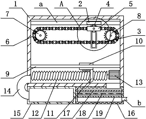
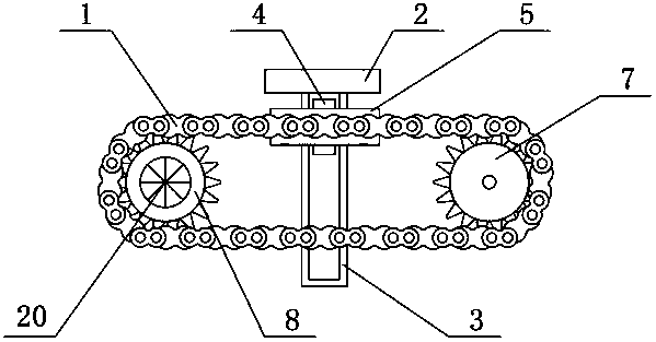
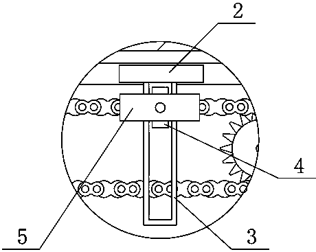
[0019] see Figure 1-3 , the present invention provides a technical solution:

[0020] A multifunctional sedimentation tank that can be automatically cleaned for road and bridge construction, including a box body 1 and a chute a, the inside of the box body 1 is provided with a chute a, and the inside of the chute a is slidably connected with a sliding plate 2, The bottom end of the sliding plate 2 is fixedly connected with a fixed frame 3, the i...


PUM


Abstract

The invention relates to the technical field of construction equipment, particularly a multi-functional sedimentation tank capable of automatic cleaning and used for road and bridge construction. Thesedimentation tank comprises a tank body and a sliding slot. The inside of the tank body is provided with the sliding slot. The inside of the sliding slot is slidingly connected to a sliding plate. The bottom end of the sliding plate is fixedly connected to a fixing rack. The inside of the sliding rack is slidingly connected to a sliding block. The rear end surface of the sliding block is fixedlyconnected to a chain. The inside of the tank body is fixedly connected to a fixing bar. The rear end surface of the fixing bar is slidingly connected to a supporting plate. The bottom end of the supporting plate is fixedly connected to a cleaning plate and is rotatably connected to a rotating shaft. The rotating shaft is simple in configuration, easy to produce, stable in transmission, low in noise, and convenient and rapid to use. Dirt at the bottom of the sedimentation tank can be removed well. Dir can be removed conveniently, time and labor are saved, and the sedimentation tank has huge economic benefit and a wide market prospect, and deserves promotion and application.

Description

technical field [0001] The invention relates to the technical field of construction equipment, in particular to a multifunctional sedimentation tank that can be automatically cleaned for road and bridge construction. Background technique [0002] The sedimentation tank is a structure that uses sedimentation to remove suspended solids in water. It is an equipment for purifying water quality. It uses the natural precipitation of water or the effect of coagulation and sedimentation to remove suspended solids in water. However, it is more troublesome to clean up the stolen goods after sedimentation. Therefore, There is an increasing demand for multi-functional road and bridge construction with self-cleaning sedimentation tanks. [0003] Most of the road and bridge construction sedimentation tanks on the market use manual cleaning to clean up the stolen goods deposited at the bottom of the sedimentation tank, which is not only time-consuming and laborious, but also the cleaning e...

Claims


Application Information

Patent Timeline
IPC IPC(8): B01D36/04C02F9/02
CPCB01D36/04C02F1/001C02F1/52C02F2001/007
Inventor 莫显坤
Owner GUILIN SHIHUAN WASTE GAS TREATMENT EQUIP
Why Eureka
Try Eureka