No-wire-harness connection structure

A connection structure and wireless technology, which is applied in the direction of support structure installation, electrical equipment construction parts, electrical components, etc., can solve the problems of low aesthetics, small space for aerial insertion welding, and reduced production availability, so as to avoid welding too many lines Cables and layouts are highly consistent, avoiding wiring errors

Pending Publication Date: 2018-09-21
HENAN THINKER TRACK TRAFFIC TECH RES INST
View PDF6 Cites 1 Cited by
  • Summary
  • Abstract
  • Description
  • Claims
  • Application Information

AI Technical Summary

Problems solved by technology

[0004] 1. The signal is drawn out by the wire tie, and the two ends need to be welded, which wastes manpower, increases working hours, and increases costs
[0005] 2. During mass production, cable connections are prone to human errors, which reduces production availability
[0006] 3. Some sensitive signals are susceptible to interference by cable length and routing position, which affects signal quality and reduces product performance
[0007] 4. When there are many cables, it will increase the difficulty of later debugging and maintenance, and reduce the maintainability
[0008] 5. The overall process aesthetics in the cable connection chassis is low
[0010] 7. When there are many front-end plug-ins, the welding space of the aviation plug is small, and it is difficult to choose a suitable aviation plug to meet the requirements

Method used


Image

  • No-wire-harness connection structure
  • No-wire-harness connection structure
  • No-wire-harness connection structure

Examples


Embodiment Construction

[0033] The present invention will be described in further detail below in conjunction with the accompanying drawings and specific embodiments.

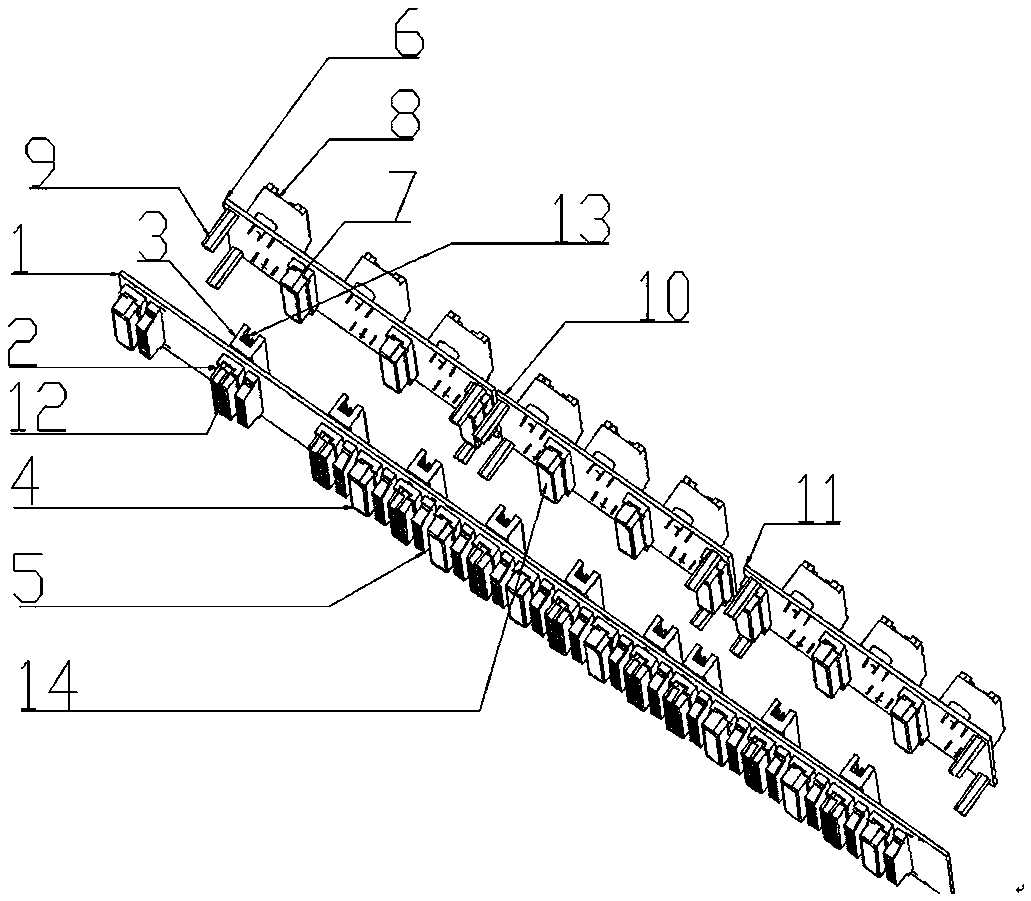
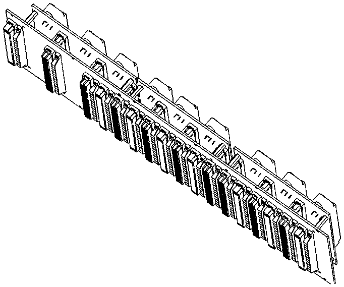
[0034] The invention provides a wireless binding device applied in a case, which is used for optimizing the wiring inside the case.

[0035] The device of the present invention includes a motherboard 1 and a backplane, and the motherboard 1 is provided with a long-pin connector L2. Both the above-mentioned setting method and the following setting method can choose a fixed setting method or a non-fixed setting method, and a welding method can be selected for a fixed setting method.

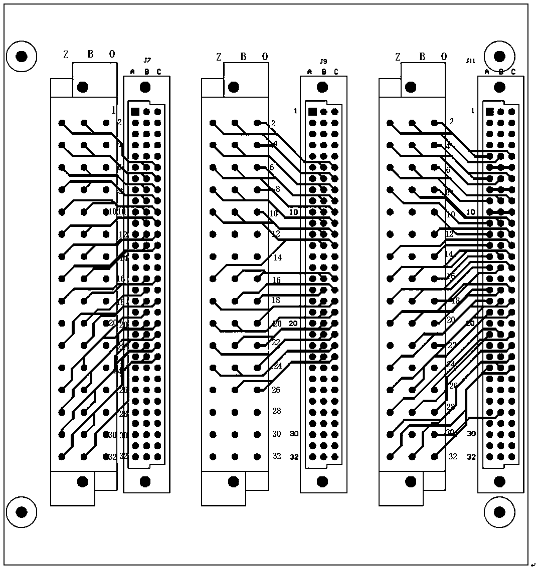
[0036] The connector pins of the connector L2 penetrate the other side of the motherboard 1, and then penetrate the other side of the backplane connected to the motherboard 1, and then connect to the connector M8 through the printed lines on the backplane.

[0037] That is, the printed lines are arranged on the backboard of the present invention, and the ...


PUM


Abstract

The invention provides a no-wire-harness connection structure comprising a motherboard 1 and a backboard. One side of the motherboard is provided with a connector L. One side of the backboard is provided with a connector M. The connector pins of the connector L are inserted through the other side of the motherboard and then inserted through the other side of the backboard connected with the motherboard and then connected with the connector M through the printed lines on the backboard. According to the structure, the wire harness can be omitted, signal switching can be directly completed through inserting connection between the motherboard and the backboard and the objective of no-cable connection of the device can be achieved; and switching of the signal required to be led out is completedthrough the printed lines between the connectors, and the connector pin description can be freely designed according to actual user application.

Description

technical field [0001] The invention belongs to the field of electronics and electricity, and in particular relates to a wireless tie connection device. Background technique [0002] During the design process of the chassis, we often encounter the problem of wiring the external interface signals of the chassis. At present, there are also various forms of signal wiring inside the chassis, and the main implementation schemes are as follows: 1. Use welding cables to lead the external communication signal of the motherboard to the connector on the rear panel; 2. Solder the aviation plug on the back of the motherboard or Using the electrical connection between the aviation plug printed board and the motherboard, the external signal is transferred and then led out through the aviation plug. [0003] At present, the commonly used internal wiring methods of the chassis mainly have the following disadvantages: [0004] 1. The wire tie leads to the signal, and the two ends need to b...

Claims


Application Information

Patent Timeline
Patent Type & Authority Applications(China)
IPC IPC(8): H05K7/14
CPCH05K7/1447H05K7/1452
Inventor 刘传华齐东坤李冠军王灿苏慧祥
Owner HENAN THINKER TRACK TRAFFIC TECH RES INST
Why Eureka
Try Eureka