
Patsnap Eureka
For R&D, Patsnap Eureka makes reading and utilizing patents & technical documents easy.
Patsnap Eureka AIR
Designed for self-driven R&D workflows. Generate viable solutions, solve complex R&D challenges, empower your innovation with AI.

Patsnap Eureka Materials
Designed for material experts only. Revolutionize your material R&D, from search, analyze, to developing new materials.

TechResearch
Generate reliable direction feasibility study reports for your R&D in just a few steps.

TechSeek
Discover and master advanced knowledge NOW. Basics, ideas, possibilities, all at once.

TechMind
As an expert in R&D Theories, TechMind can generates customized viable solutions instantly.

TechRisk
Analyze your overall solution with one click, know your potential R&D risks in advance.

TechMonitor
Get weekly tech updates, stay abreast of the latest tech innovations and key insights.
An electric water pump and water gun structure
A technology of electric water pumps and transmission mechanisms, applied in pumps, pump components, pump control, etc., can solve problems such as high requirements for power supply equipment, high price of high-power motors, and large volume
- Summary
- Abstract
- Description
- Claims
- Application Information
AI Technical Summary
Problems solved by technology
Method used
Image

Examples
Embodiment 1
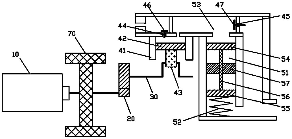
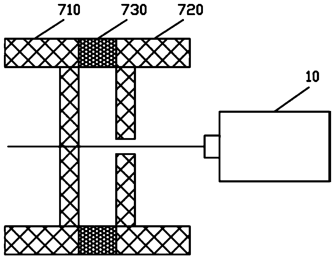
[0033] Such as figure 1 As shown, an electric water pump of the present invention includes a motor 10, a gear set 20, a transmission mechanism 30, a piston mechanism and a stroke changing mechanism. The output shaft of the motor 10 is connected to the transmission mechanism 30 through the gear set 20, and the transmission mechanism 30 is connected to For the piston mechanism (in practical application, the piston mechanism adopts a single-piston structure), the piston mechanism includes a piston cylinder 41, a piston body 42 is arranged in the piston cylinder 41, the piston body 42 is connected to the transmission mechanism 30 through the piston rod 43, and the transmission mechanism 30 passes The piston rod 43 drives the piston body 42 to move up and down. The piston cylinder 42 is provided with a water outlet 44 and a water inlet 45. The water outlet 44 is provided with a water outlet valve 46, and the water inlet is provided with a water inlet valve 47. Specifically, the pist...
Embodiment 2
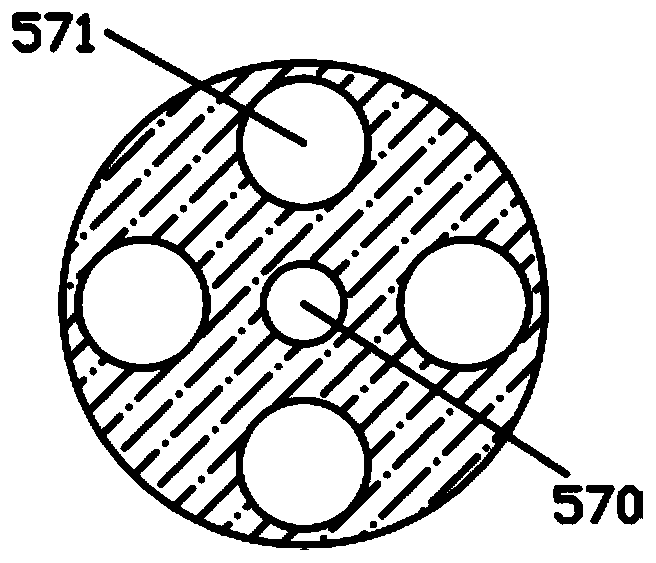
[0045] Such as Figure 9 As shown, in this embodiment, the water flow buffer chamber 51 is arranged in an I-shaped structure cooperating with the movable components, and the number of baffles 57 is reduced. During work, the upper movable plate 54 is pushed downward by the water flow driven by the piston body 42, and the upper movable plate 54 can close the water flow hole 571 after contacting the water flow hole 571 to realize the closure of the drainage bypass. After the energy is released, the water flow The drainage bypass formed by the buffer cavity 51 loses resistance, the lower movable plate 55 is pushed upward by the elastic force of the spring 52, and after the upper movable plate 54 is separated from the baffle plate 57, the water flow hole 570 can be opened to start the drainage bypass. The function of the water flow hole 571 is to let water flow through. It should be noted that the diameter of the water flow hole 571 must be smaller than the area of the upper mov...
Embodiment 3
[0048] Such as Figure 10 As shown, in this embodiment, a side hole 58 is opened on the side wall of the piston cylinder 41, and a simple drainage channel is communicated through the side hole 58, thereby reducing movable components, which mainly pass through the side hole 58 of the piston body 42. The opening and closing of the drainage channel is realized. When the motor 10 is working, the gear set 20 and the transmission mechanism 30 push the piston body 42 to move upwards. At this time, the piston mechanism is in the drainage stroke. Since the drainage bypass formed by the drainage channel has little resistance to the water flow, (that is, the water flow is easy to flow beside the drainage. flow in the middle of the road), and the resistance of the water outlet 44 to the water flow is much greater than the resistance of the drainage channel to the water flow, the water inside the piston cylinder 41 is pushed to discharge through a path without resistance, that is, it is di...
PUM
 Abstract
Description
Claims
Application Information
 - R&D Engineer
- R&D Manager
- IP Professional
- Industry Leading Data Capabilities
- Powerful AI technology
- Patent DNA Extraction
Browse by: Latest US Patents, China's latest patents, Technical Efficacy Thesaurus, Application Domain, Technology Topic, Popular Technical Reports.
© 2024 PatSnap. All rights reserved.Legal|Privacy policy|Modern Slavery Act Transparency Statement|Sitemap|About US| Contact US: help@patsnap.com