
A strap winding machine for hammock straps

A tape winding machine and strapping technology, which is applied in the direction of winding strips, thin material processing, transportation and packaging, etc., can solve the need for manual work of the tape winding machine, limit the length of the tape of the tape winding machine, and cannot measure the tape length and other issues to achieve the effect of reducing production costs, improving accuracy and improving work efficiency

Active Publication Date: 2019-09-06
安徽省乐悠悠户外用品有限公司
View PDF6 Cites 0 Cited by
  • Summary
  • Abstract
  • Description
  • Claims
  • Application Information

AI Technical Summary

Problems solved by technology

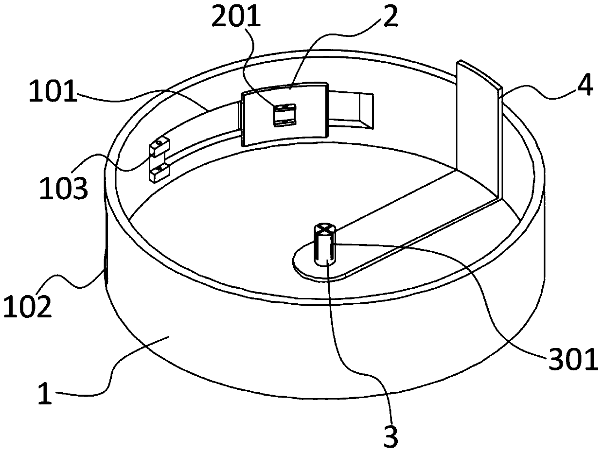
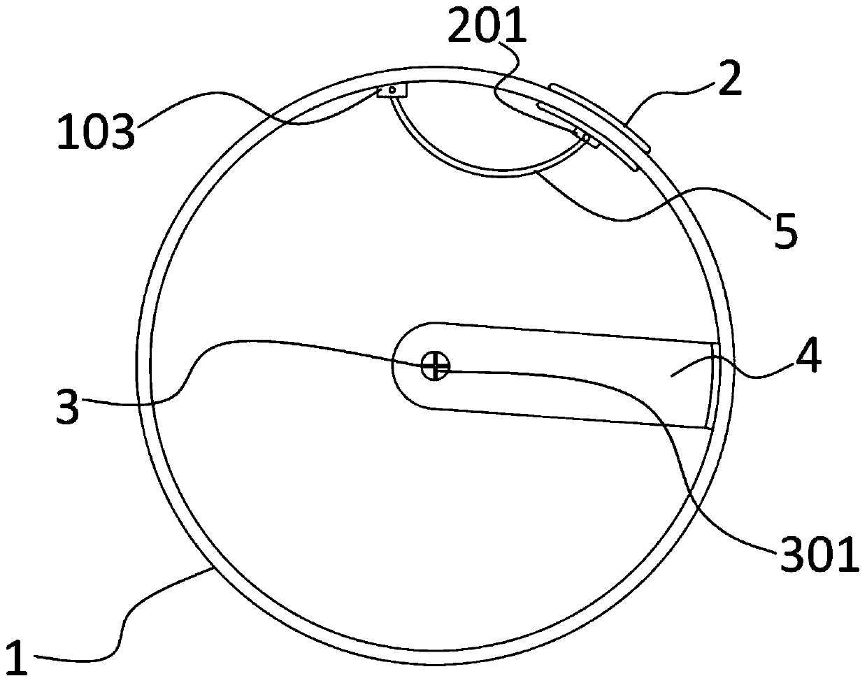
[0003] The object of the present invention is to provide a belt winding machine for hammock straps. A rotating shaft is arranged at the bottom of the strap winding machine, one end of the strap is fixed by the rotating shaft and the motor drives the rotating shaft to rotate rapidly, The block slides to drive the deformation of the elastic sheet, which reduces the space in the tape winding machine and limits the tape length of the tape tape machine. It solves the problems that the existing tape tape machine requires manual work and cannot measure the tape length.

Method used

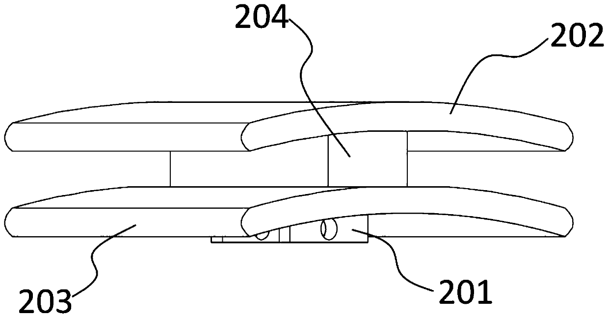

Image

  • A strap winding machine for hammock straps
  • A strap winding machine for hammock straps
  • A strap winding machine for hammock straps

Examples


Embodiment Construction

[0022] The following will clearly and completely describe the technical solutions in the embodiments of the present invention with reference to the accompanying drawings in the embodiments of the present invention. Obviously, the described embodiments are only some, not all, embodiments of the present invention. Based on the embodiments of the present invention, all other embodiments obtained by persons of ordinary skill in the art without creative efforts fall within the protection scope of the present invention.

[0023] In describing the present invention, it is to be understood that the terms "opening", "upper", "lower", "thickness", "top", "middle", "length", "inner", "surrounding" etc. Indicating orientation or positional relationship is only for the convenience of describing the present invention and simplifying the description, and does not indicate or imply that the components or elements referred to must have a specific orientation, be constructed and operated in a sp...


PUM


Abstract

The invention discloses a strip rolling machine used for a hammock binding strip and relates to the field of strip rolling machine manufacturing. The strip rolling machine used for the hammock bindingstrip comprises a shell, a slider, a lifting plate and an elastic thin sheet; the axis position of the bottom face of the shell is provided with a rotating shaft; one end of the rotating shaft is connected with a motor; the peripheral side of the shell is provided with a sliding port in the radial direction; the peripheral side of the shell is provided with a strip inlet in the axial direction; afirst hinged base is arranged at the edge position of the strip-shaped sliding port in the inner side of the shell; the slider comprises an upper sliding plate and a lower sliding plate; the upper sliding plate and the lower sliding plate are connected and fixed through a connection block; the opposite face, connected with the connection block, of the lower sliding plate is provided with a secondhinged base; and the two ends of the elastic thin sheet are hinged to the first hinged base and the second hinged base correspondingly. According to the strip rolling machine used for the hammock binding strip, due to the fact that the rotating shaft is arranged at the bottom of the strip rolling machine, the rotating shaft is used for fixing one end of the binding strip, and the motor is used for driving the rotating shaft to fast rotate; the slider on the peripheral side of the strip rolling machine slides and drives the elastic thin sheet to deform so that the space in the strip rolling machine can be reduced, and therefore the strip rolling length of the strip rolling machine is limited, the production efficiency is improved, and the production cost is reduced.

Description

technical field [0001] The invention belongs to the field of winding machine manufacturing, in particular to a winding machine used for binding straps of a hammock. Background technique [0002] Most of the bandages and adhesive tapes produced by today's factories and enterprises adopt manual tape roll operations. One end of the tape is placed on the tape reel, and the workers manually rotate the reel to roll up the tape. Obviously, this way of working is labor-intensive and low-efficiency. In addition, because the tape roll will cause wear and knots on the ground, it will inevitably cause stoppage of operations. Moreover, if there is a requirement for the length of the tape, it is difficult to determine the length of the bandage through the naked eye in the traditional manual tape operation. It can be seen that the traditional method of using manual tape is not suitable for the rapid operation of modern enterprise factories. . Contents of the invention [0003] The obj...

Claims


Application Information

Patent Timeline
Patent Type & Authority Patents(China)
IPC IPC(8): B65H18/10B65H75/18
Inventor 段照林
Owner 安徽省乐悠悠户外用品有限公司
Learn More