
Scanning projection method of laser scanning projector

A laser scanning and projector technology, which is applied in the direction of using the image reproducer of the projection device, the parts and electrical components of the color TV, etc., can solve the problem of wrong image projection, etc., and achieve the effect of eliminating the projection effect.

Inactive Publication Date: 2018-09-14
GOERTEK OPTICAL TECH CO LTD
View PDF6 Cites 4 Cited by
  • Summary
  • Abstract
  • Description
  • Claims
  • Application Information

AI Technical Summary

Problems solved by technology

[0005] In view of the above problems, the purpose of the present invention is to provide a scanning projection method of a laser scanning projector, to solve the problem of wrong image projection caused by the intersecting oblique lines after the back and forth scanning of the existing laser scanning projector

Method used


Image

  • Scanning projection method of laser scanning projector
  • Scanning projection method of laser scanning projector
  • Scanning projection method of laser scanning projector

Examples


Embodiment Construction

[0036] In the following description, for purposes of explanation, numerous specific details are set forth in order to provide a thorough understanding of one or more embodiments. It may be evident, however, that these embodiments may be practiced without these specific details.

[0037] Specific embodiments of the present invention will be described in detail below in conjunction with the accompanying drawings.

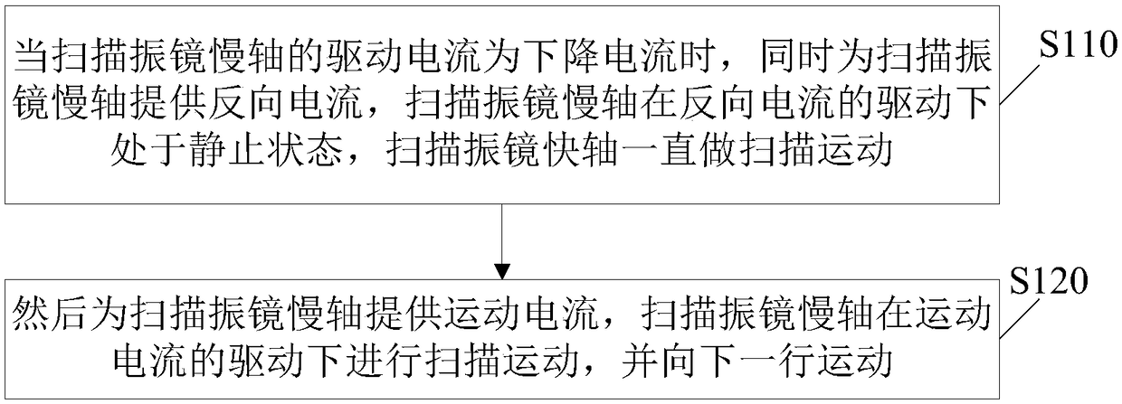
[0038] In order to illustrate the scanning projection method of the laser scanning projector according to the embodiment of the present invention provided by the present invention, figure 1 The flow of the scanning projection method of the laser scanning projector according to the embodiment of the present invention is shown.

[0039] Such as figure 1 As shown, the scanning projection method of the laser scanning projector provided by the present invention includes:

[0040] Scanning is performed through the fast axis of the scanning galvanometer and the slow axis ...


PUM


Abstract

The invention provides a scanning projection method of a laser scanning projector. The scanning projection method comprises the following steps: performing scanning through a scanning galvanometer fast axis and a scanning galvanometer slow axis of the laser scanning projector, wherein the scanning mode of the scanning galvanometer slow axis is a nonlinear motion scanning mode; in a process of scanning each row, the scanning galvanometer slow axis is enabled to be in a static state at a preset position by regulating and controlling driving current; when the driving current of the scanning galvanometer slow axis is drop-out current, reverse current is provided for the scanning galvanometer slow axis, so that the scanning galvanometer slow axis is in the static state under the driving of thereverse current, and the scanning galvanometer fast axis does scanning motion all the time; and then, motion current is provided for the scanning galvanometer slow axis, so that the scanning galvanometer slow axis does the scanning motion under the driving of the motion current and moves to the next row. By use of the scanning projection method of the laser scanning projector, the problem of wrongimage projection caused by intersecting diagonals formed by back-and-forth scanning of the existing laser scanning projector can be solved.

Description

technical field [0001] The present invention relates to the technical field of laser scanning projectors, and more specifically, to a scanning projection method of a laser scanning projector. Background technique [0002] The core device in the laser scanning projector is the scanning galvanometer, which is divided into fast axis scanning and slow axis scanning. In the fast axis direction, the fast resonance of the MEMS mirror is used to realize the scanning. Now, the laser light source is used to incident on the MEMS mirror, and two lines of images will be projected after a cycle scanning back and forth of the MEMS mirror. [0003] However, because the slow axis is moving at a constant speed, this will cause the two lines projected by scanning back and forth to be not parallel to each other, but an angled intersecting oblique line. These oblique lines that scan back and forth can cause wrong image projections. [0004] Therefore, in order to solve the above problems, the ...

Claims


Application Information

Patent Timeline
Patent Type & Authority Applications(China)
IPC IPC(8): H04N9/31
CPCH04N9/3102H04N9/312
Inventor 杨乐宝
Owner GOERTEK OPTICAL TECH CO LTD
Learn More