
Mounting-facilitating transformer

A transformer and installation groove technology, which is applied in the direction of transformer/inductor corrosion protection, transformer/reactor installation/support/suspension, etc. It can solve the problems of poor use effect, loss of effect, heavy transformer, etc.

Pending Publication Date: 2018-09-14
栗斌
View PDF0 Cites 3 Cited by
  • Summary
  • Abstract
  • Description
  • Claims
  • Application Information

AI Technical Summary

Problems solved by technology

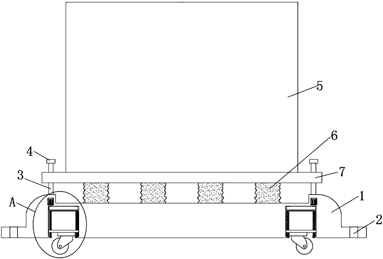
[0004] The purpose of the present invention is to solve the problem that technicians in the prior art will install some shock-absorbing layers between the bottom of the transformer and the mounting plate when installing the transformer, but the existing shock-absorbing layers are often some shock-absorbing pads, the effect of which is It disappears after a period of use, because the weight of the transformer itself has been acting on the shock-absorbing pad, so the shock-absorbing pad is deformed under pressure, and gradually loses its effect, and the use effect becomes worse. At the same time, the transformer itself is heavy and not easy to move problems, and a transformer that is easy to install is proposed

Method used


Image

  • Mounting-facilitating transformer
  • Mounting-facilitating transformer
  • Mounting-facilitating transformer

Examples


Embodiment Construction

[0021] The following will clearly and completely describe the technical solutions in the embodiments of the present invention with reference to the accompanying drawings in the embodiments of the present invention. Obviously, the described embodiments are only some, not all, embodiments of the present invention.

[0022] In describing the present invention, it should be understood that the terms "upper", "lower", "front", "rear", "left", "right", "top", "bottom", "inner", " The orientation or positional relationship indicated by "outside", etc. is based on the orientation or positional relationship shown in the drawings, and is only for the convenience of describing the present invention and simplifying the description, rather than indicating or implying that the referred device or element must have a specific orientation, so as to Specific orientation configurations and operations, therefore, are not to be construed as limitations on the invention.

[0023] refer to Figure ...


PUM


Abstract

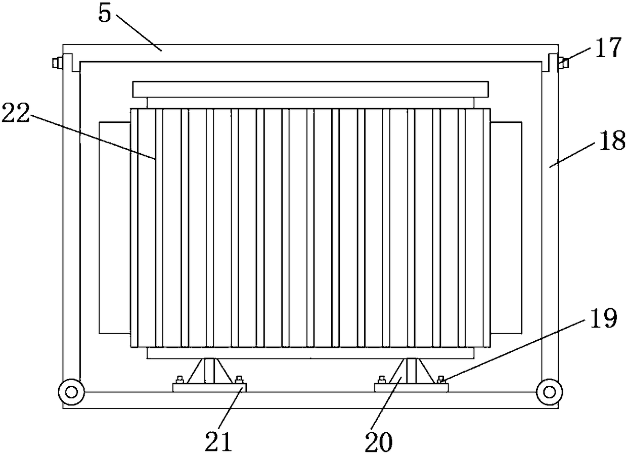
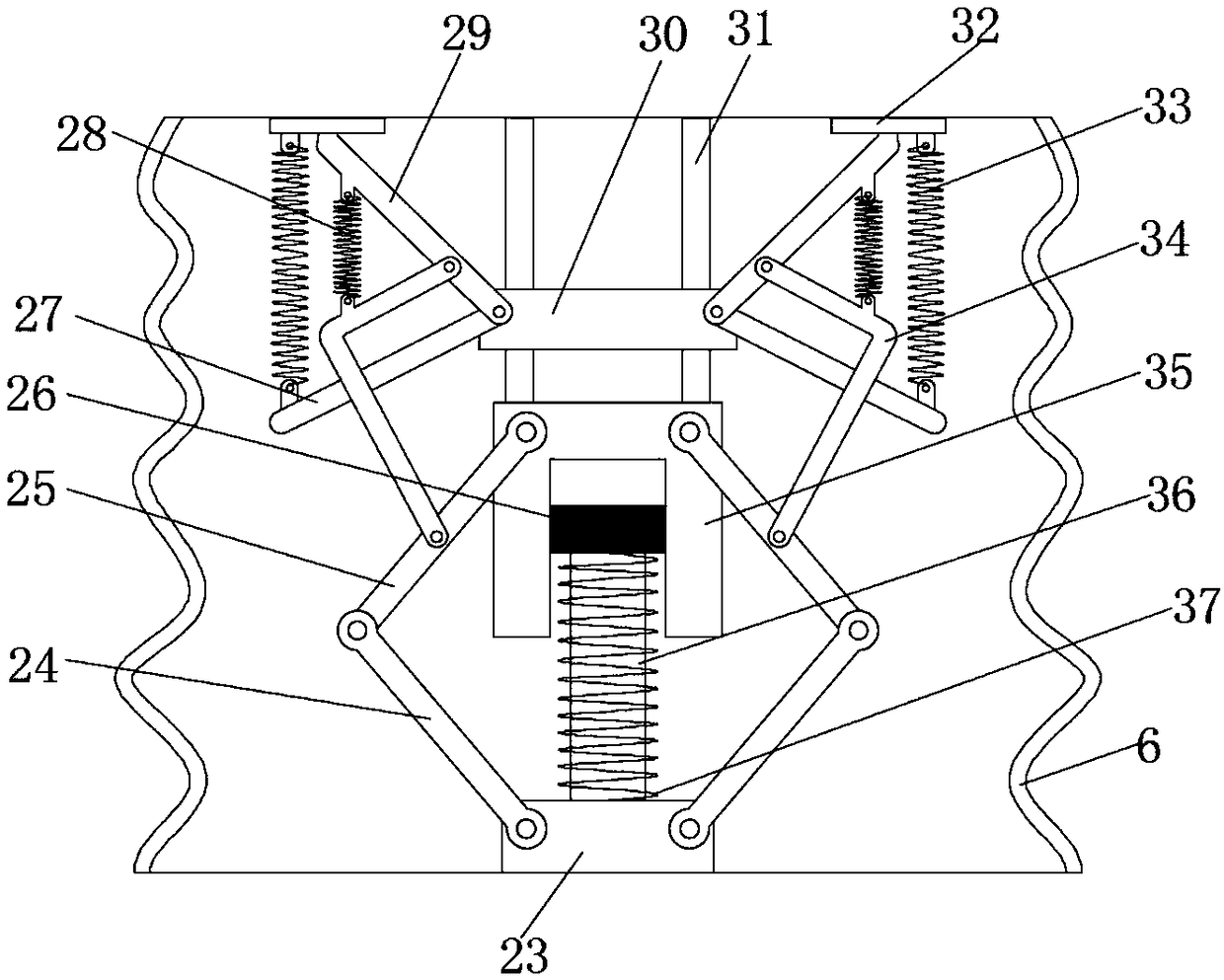
The invention discloses a mounting-facilitating transformer, which comprises a base, wherein multiple mounting holes are symmetrically formed in the base; four mounting slots are uniformly formed in the lower surface of the base; two grooves are symmetrically formed in the inner wall of each mounting slot; four first cavities and four second cavities are symmetrically formed in the base; a motor is arranged in each second cavity; a limiting rod is arranged in each groove; a fixed block is arranged on two limiting rods; supporting frames are arranged on the fixed blocks; the supporting frames are connected with rolling wheels in a rotatable manner; the fixed blocks are in threaded connection with two threaded rods. The mounting-facilitating transformer disclosed by the invention is simple in structure and convenient to use; by the arrangement of the rolling wheels, the transformer can move conveniently; furthermore, the rolling wheels can be collected into the mounting slots, so as to not affect the mounting of the transformer; meanwhile, by the arrangement of a vibration absorption device, damage to the transformer due to vibration generated in a moving process is reduced; by the arrangement of multiple different springs, the vibration absorption effect is guaranteed; the service life is prolonged; the transformer is worthy of being popularized.

Description

technical field [0001] The invention relates to the technical field of power equipment, in particular to a transformer that is easy to install. Background technique [0002] Power equipment mainly includes power generation equipment and power supply equipment. Power generation equipment is mainly power plant boilers, steam turbines, gas turbines, water turbines, generators, transformers, etc. Power supply equipment is mainly transmission lines of various voltage levels, transformers, contactors, etc. device and so on. [0003] Transformer is a device that uses the principle of electromagnetic induction to change AC voltage. The main components are primary coil, secondary coil and iron core. The main functions are: voltage conversion, current conversion, impedance conversion, isolation, voltage stabilization, etc., which can be divided according to the purpose For: power transformers and special transformers, the transformer is an electrical component, it is greatly damaged ...

Claims


Application Information

Patent Timeline
IPC IPC(8): H01F27/06H01F27/23
CPCH01F27/06H01F27/23
Inventor 林声坤陈炳哲刘小静
Owner 栗斌
Learn More