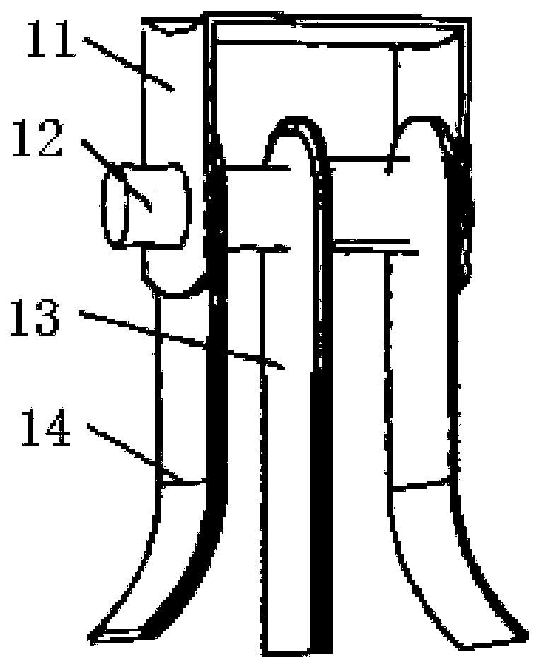
Straw pulverizer

A technology of straw shredders and racks, which is applied to harvesters, agricultural machinery and implements, cutters, etc., can solve the problems of increasing hammer claw wear and power consumption, and achieves the effect of high crushing rate and good stubble removal rate

Inactive Publication Date: 2018-09-14
赵文兵
View PDF0 Cites 2 Cited by
  • Summary
  • Abstract
  • Description
  • Claims
  • Application Information

AI Technical Summary

Problems solved by technology

[0003] The traditional straw crushing and returning machine mainly uses the hammer claw to cut the straw. This way will make the hammer claw contact with the soil, which will increase the wear and power consumption of the hammer claw.

Method used


Image

  • Straw pulverizer
  • Straw pulverizer
  • Straw pulverizer

Examples


Embodiment 1

[0015] Example 1, see figure 1 , the straw grinder of the present invention comprises a frame 1, an engine 2, a gearbox 3, a main shaft 4, a saw disc cutter shaft 5, a saw blade 6, a knife shaft 7, a knife 8 and a suspension device 9, and the frame 1 consists of The base plate, the cover plate, the left side plate and the right side plate are enclosed, the left side plate is provided with the left mounting hole of the saw disc cutter shaft and the left mounting hole of the swing knife shaft, and the right side plate is provided with the saw disc cutter shaft The right mounting hole, the right mounting hole of the knife shaft and the main shaft mounting hole, the engine mounting groove is arranged on the bottom plate of the frame 1, the engine 2 is installed in the engine mounting groove, the output shaft of the engine 2 is connected with the main shaft 4 through the gearbox 3, The other end of the main shaft 4 extends out of the main shaft installation hole, one end of the saw...


PUM


Abstract

The invention discloses a straw pulverizer, and belongs to the technical field of agricultural machinery. The technical scheme of the invention is that the straw pulverizer comprises a frame, an engine, a gearbox, a main shaft, a saw disc cutter shaft, saw blades, a swinging cutter shaft, swinging cutters and a suspension device. The straw pulverizer has the beneficial effects that the crushing rate is high, and the scattering unevenness and the stubble cleaning rate are good.

Description

technical field [0001] The invention belongs to the technical field of agricultural machinery, and in particular relates to a straw pulverizer. Background technique [0002] The sown area of ​​corn in my country is about 20000khm 2 , the handling of corn stover after corn harvest is a key issue. Studies have shown that the land after straw returning has greatly increased the organic matter content in the soil, enhanced the microbial activity in the soil, and increased the yield of crops. Therefore, it is particularly important to use straw crushing and returning machines for straw returning. [0003] The traditional straw crushing and returning machine mainly uses the hammer claw to cut the straw. This method will make the hammer claw contact with the soil, which will increase the wear and power consumption of the hammer claw. Contents of the invention [0004] Aiming at the above-mentioned technical problems, the present invention provides a straw grinder. The straw gri...

Claims


Application Information

Patent Timeline
IPC IPC(8): A01D43/08
CPCA01D43/08
Inventor 赵文兵
Owner 赵文兵
Why Eureka
Try Eureka