
Fingerprint recognition device and display equipment

A fingerprint recognition and fingerprint technology, applied in character and pattern recognition, acquisition/organization of fingerprints/palmprints, instruments, etc., can solve problems such as thick display thickness and complex structure

Inactive Publication Date: 2018-09-11
BOE TECH GRP CO LTD
View PDF6 Cites 14 Cited by
  • Summary
  • Abstract
  • Description
  • Claims
  • Application Information

AI Technical Summary

Problems solved by technology

[0003] In the display devices of the prior art, the structure used for fingerprint recognition generally includes a small hole filter structure, a lens and a grating structure. Although it can obtain fingerprint information, the structure is too complicated, resulting in the problem that the overall display thickness is too thick

Method used


Image

  • Fingerprint recognition device and display equipment
  • Fingerprint recognition device and display equipment
  • Fingerprint recognition device and display equipment

Examples


Embodiment Construction

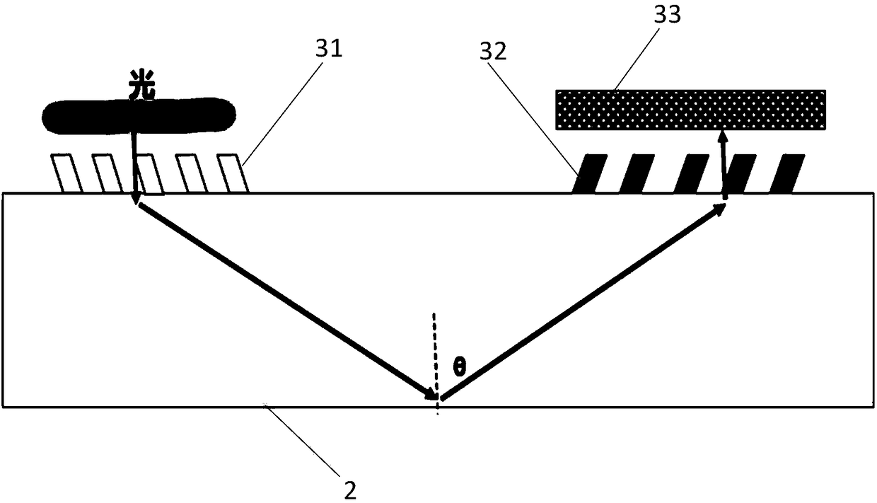
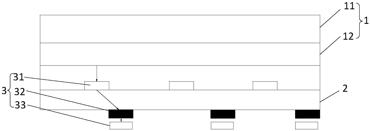
[0022] In order to further explain the technical means and effects of the present invention to achieve the intended purpose of the invention, the specific implementation, structure, features and effects of the fingerprint identification device proposed according to the present invention will be described below in conjunction with the accompanying drawings and preferred embodiments. Details are as follows.

[0023] Such as figure 1 , figure 2 As shown, the embodiment of the present invention provides a fingerprint identification device, including:

[0024] Light-transmitting substrate 1;

[0025] A light guide layer 2, the light guide layer 2 is arranged on one side of the light-transmitting substrate 1;

[0026] A plurality of identification units 3, a plurality of identification units 3 are arranged on the light guide layer 2, each identification unit 3 includes a first grating module 31, a second grating module 32 and a detection module 33; wherein,

[0027] The first g...


PUM


Abstract

The invention discloses a fingerprint recognition device and display equipment, and relates to the technical field of display, so as to achieve the simple structure of the fingerprint recognition device, and to enable the fingerprint recognition device to be light and thin. The main technical scheme of the invention is that the fingerprint recognition device comprises a transparent substrate; a light guide layer which is disposed at one side of the transparent substrate; a plurality of recognition units which are disposed on the light guide layer, wherein each recognition unit comprises a first optical grating module, a second optical grating module, and a detection module. The first optical grating module is disposed between the light guide layer and the transparent substrate, and is usedfor enabling the fingerprint light with an incidence angle being within a preset angle range to be diffracted and coupled to the interior of the light guide layer for transmission. The second opticalgrating module is disposed at one side of the light guide layer, and the detection module is disposed at a side, backing on to the light guide layer, of the second optical grating module. The secondoptical grating module is used for extracting the fingerprint light in the light guide layer to the detection module. The detection module is used for detecting the light intensity of the fingerprintlight. The device is mainly used for fingerprint recognition.

Description

technical field [0001] The invention relates to the field of display technology, in particular to a fingerprint identification device and a display device. Background technique [0002] With the rapid development of display technology, the functions of display devices are gradually increasing. Among them, in addition to image display, display devices can also have fingerprint recognition functions to improve the security of display devices and improve the convenience of fingerprint verification. . [0003] In the display devices of the prior art, the structure used for fingerprint recognition generally includes a small hole filter structure, a lens and a grating structure. Although it can obtain fingerprint information, the structure is too complicated, resulting in the problem that the overall display thickness is too thick . Contents of the invention [0004] In view of this, an embodiment of the present invention provides a fingerprint identification device and a disp...

Claims


Application Information

Patent Timeline
IPC IPC(8): G06K9/00
CPCG06V40/1324H10K59/65G06V40/1318H10K59/40
Inventor 孟宪东王维陈小川王海生顾品超高健
Owner BOE TECH GRP CO LTD
Learn More