
Combined vibration mixed particle layering device

A layering device and particle technology, applied in classification, solid separation, chemical instruments and methods, etc., can solve problems such as complex mechanism, low working efficiency of combined vibration mechanism, inability to improve efficiency, strengthen layering effect, etc., to achieve The effect of simple overall structure

Active Publication Date: 2018-09-11
UNIV OF SCI & TECH LIAONING
View PDF19 Cites 6 Cited by
  • Summary
  • Abstract
  • Description
  • Claims
  • Application Information

AI Technical Summary

Problems solved by technology

With the in-depth research on mixed particulate matter, allowing mixed particulate matter to move in a single direction can no longer meet the needs of improving efficiency and strengthening the layering effect
[0003] Due to the different vibration sources and vibration methods used in the existing combined vibration technology, the effects produced are also different, and most of the combined vibration mechanisms have low working efficiency, need to be disassembled repeatedly, and the separation effect of mixed particles is not ideal. Especially for the observation of the "Brazil nut" phenomenon of separation of large and small particles, it is not obvious and intuitive
For example: the Chinese patent "an electric combined vibration type grain grading device" whose publication number is CN106179950A adopts "swing guide rod mechanism + crank slider mechanism" to realize combined vibration, but its mechanism is relatively complicated and has no effect on the separation of large and small particles. obvious and intuitive

Method used


Image

  • Combined vibration mixed particle layering device
  • Combined vibration mixed particle layering device
  • Combined vibration mixed particle layering device

Examples


Embodiment Construction

[0021] The specific implementation manner of the present invention will be further described below in conjunction with the accompanying drawings.

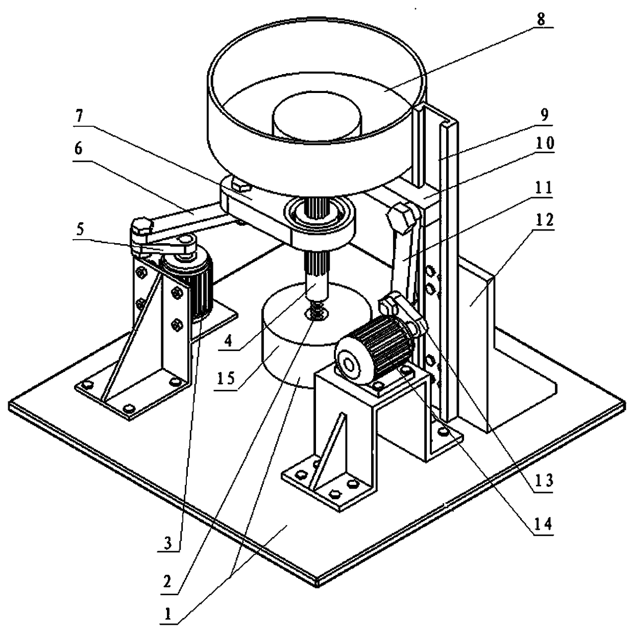
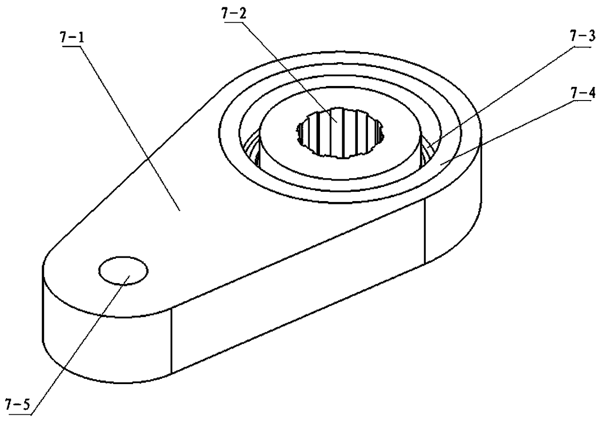
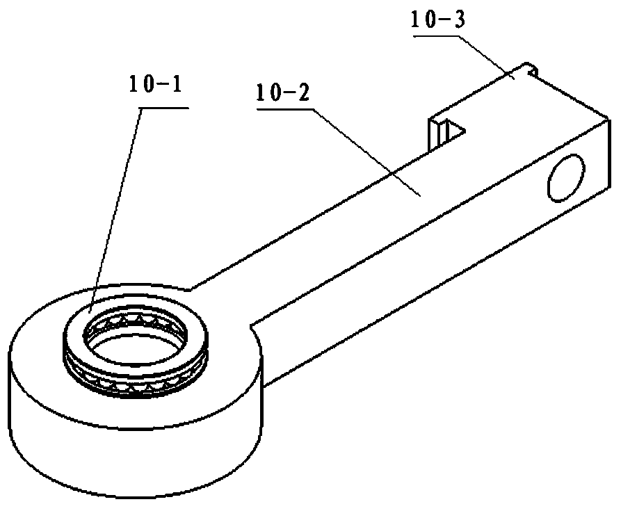
[0022] Such as figure 1 , 2 Shown in and 3, the combination vibration mixing particle stratification device of the present invention is characterized in that comprises base 1, is arranged on the bin mechanism on this base 1, the crank rocker mechanism that is connected with this bin mechanism, and described The crank slider mechanism connected with the silo mechanism,

[0023] The silo mechanism includes a material silo 8, a rotating shaft 4 arranged below the material silo 8, a fixed seat 15 arranged on the base 1, a spring 2 connecting the rotating shaft 4 and the fixed seat 15,

[0024] The crank rocker mechanism includes a motor I3, a crank I5 hinged with the motor I3, a connecting rod I6 hinged with the crank I5, one end is hinged with the connecting rod I6, and the other end is fixed to the rotating shaft 4 Connected combi...


PUM


Abstract

The invention belongs to the technical field of screening devices, and particularly relates to a combined vibration mixed particle layering device. The combined vibration mixed particle layering device is characterized by comprising a base, a stock bin mechanism arranged on the base, a crank rocking rod mechanism connected with the stock bin mechanism, and a crank slider mechanism connected with the stock bin mechanism; the stock bin mechanism comprises a material bin, a rotating shaft, a fixed base and a spring connecting the rotating shaft with the fixed base; the crank rocking rod mechanismcomprises a motor I, a crank I, a connection rod I and a combined rocking rod with one end hinged to the connection rod I and the other end fixedly connected with the rotating shaft; and the crank slider mechanism comprises a motor II, a crank II, a connection rod II, a slide groove frame, a longitudinal slide groove and a slider with one end in sliding connection with the longitudinal slide groove and the other end fixedly connected with the rotating shaft. According to the combined vibration mixed particle layering device, circumference swinging in the horizontal direction and up-down vibration in the vertical direction are combined, combined vibration of the layering device is achieved, and the 'brazilnut' phenomenon, with large and small particles separated, of mixed particle substances under combined vibration can be observed visually.

Description

technical field [0001] The invention belongs to the technical field of screening devices, in particular to a combined vibration mixing particle layering device. Background technique [0002] As early as 1637 AD, the legendary ancient book "Tiangong Kaiwu" recorded the device used to separate grain and stalks. Stratification of mixed particles is a basic operation skill, and people continue to study and improve the mixed particle layering device. With the in-depth research on mixed particulate matter, allowing mixed particulate matter to move in a single direction can no longer meet the needs of improving efficiency and strengthening the layering effect. [0003] Due to the different vibration sources and vibration methods used in the existing combined vibration technology, the effects produced are also different, and most of the combined vibration mechanisms have low working efficiency, need to be disassembled repeatedly, and the separation effect of mixed particles is not ...

Claims


Application Information

Patent Timeline
Patent Type & Authority Applications(China)
IPC IPC(8): B07B13/00B07B13/14
CPCB07B13/00B07B13/14
Inventor 马学东郭柄江赵磊于海川丁贺贺刘正海刘海涛许家也
Owner UNIV OF SCI & TECH LIAONING
Learn More