
A bionic leg structure for legged robots

A robot and leg technology, applied in the field of bionic leg structure, can solve the problems of increasing load capacity, high energy consumption, poor environmental adaptability, etc., and achieve the effect of increasing load capacity, improving load capacity, and increasing contact area

Active Publication Date: 2017-06-06
SHAANXI JIULI ROBOT MFG
View PDF7 Cites 0 Cited by
  • Summary
  • Abstract
  • Description
  • Claims
  • Application Information

AI Technical Summary

Problems solved by technology

The leg structure adopts a rod mechanism and has two driving motors, which can reduce the weight of the legs, reduce energy consumption, and at the same time greatly increase the load capacity. In order to solve the problems of high energy consumption and poor environmental adaptability of existing legged robots The problem has laid the foundation and has a good application prospect

Method used


Image

  • A bionic leg structure for legged robots
  • A bionic leg structure for legged robots
  • A bionic leg structure for legged robots

Examples


Embodiment Construction

[0022] Further describe the present invention below in conjunction with embodiment and accompanying drawing thereof. However, the protection scope of the claims of the present application is not limited to the description scope of the embodiments.

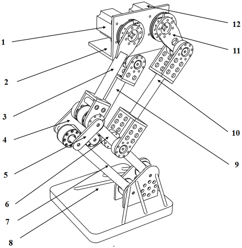
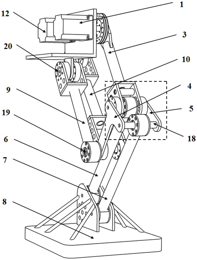
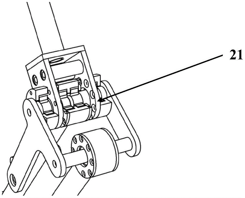
[0023] The bionic leg structure (leg structure or bionic leg for short) that can be used for legged robot designed by the present invention, see Figure 1-6 ), characterized in that the leg structure includes a lifting system, a pushing system, an auxiliary supporting system, a cooperating system and a frame 2.

[0024] The lifting system mainly includes a lifting motor 1 and a lifting rod 3 . The lifting motor 1 is fixedly connected to the frame 2 by screws; the lifting rod 3 is fixedly connected to the lifting motor 1 through a reducer, a flange, and the two rotate synchronously (see figure 1 , 2 ).

[0025] The push system mainly includes a push motor 12 , a No. 1 push rod 11 , and a No. 2 push rod 10 . The push motor 12 is...


PUM


Abstract

The invention discloses a bionic leg structure applicable to a footed robot, wherein the leg structure is based on a rod mechanism and comprises a lifting system, a thrusting system, an auxiliary supporting system, a synergic movement system, and a rack. The lifting system substantially comprises a lifting motor and a lifting rod. The lifting motor is fixedly connected with the rack. The lifting rod is fixedly connected with the lifting motor, with the lifting rod and the lifting motor being rotated synchronously. The thrusting system substantially comprises a thrust motor, a first thrusting rod, and a second thrusting rod. The thrust motor is fixedly connected with the rack. The first thrusting rod is fixedly connected with the thrust motor, with the first thrusting rod and the thrust motor being rotated synchronously. The second thrusting rod is movably connected with the first thrusting rod, with the second thrusting rod and the first thrusting rod being capable of rotating relative to each other. The auxiliary supporting system substantially comprises a first supporting rod, a second supporting rod, a third supporting rod, a first long shaft, a fourth short shaft and a fifth short shaft. The synergic movement system substantially comprises a first connecting rod, a second connecting rod, foot plates, a first short shaft, a second short shaft, and a third short shaft.

Description

technical field [0001] The invention relates to foot robot technology, in particular to a bionic leg structure that can be used for foot robots. Background technique [0002] The legged robot is an intelligent robot with redundant drive, multi-branched, and time-varying topological motion mechanism. technology product. Footed robots show strong adaptability due to their non-continuous contact with the ground during walking, especially on passages with obstacles or inaccessible work sites, so they are considered It is widely used in emergency rescue, disaster relief, mine clearance, site exploration, entertainment and civil and other fields. [0003] The robot's leg (or mechanical leg) is an important part of the robot and plays a very important role in the movement of the legged robot. However, at present, each leg of the common legged robot has 3 active degrees of freedom, and each leg requires 3 active parts. The structure is complex, the control is difficult, the cost ...

Claims


Application Information

Patent Timeline
Patent Type & Authority Patents(China)
IPC IPC(8): B62D57/032
Inventor 刘翔宇
Owner SHAANXI JIULI ROBOT MFG
Learn More