Eureka AIR delivers breakthrough ideas for toughest innovation challenges, trusted by R&D personnel around the world.

Ripple elimination circuit, ripple elimination method and LED control circuit applying ripple elimination circuit

A ripple elimination and circuit technology, applied in the field of power electronics, can solve problems such as LED current fluctuation, and achieve the effect of good load current, simple and effective control method, and ripple elimination.

Pending Publication Date: 2018-09-07
JOULWATT TECH INC LTD
View PDF0 Cites 4 Cited by
  • Summary
  • Abstract
  • Description
  • Claims
  • Application Information

AI Technical Summary

Problems solved by technology

[0004] The object of the present invention is to provide a ripple elimination circuit, elimination method and LED control circuit using the ripple elimination effect, which are used to solve the problem of LED current fluctuations in the prior art

Method used


Image

  • Ripple elimination circuit, ripple elimination method and LED control circuit applying ripple elimination circuit
  • Ripple elimination circuit, ripple elimination method and LED control circuit applying ripple elimination circuit
  • Ripple elimination circuit, ripple elimination method and LED control circuit applying ripple elimination circuit

Examples


Embodiment Construction

[0030] Preferred embodiments of the present invention will be described in detail below with reference to the accompanying drawings, but the present invention is not limited to these embodiments. The present invention covers any alternatives, modifications, equivalent methods and schemes made within the spirit and scope of the present invention.

[0031] In order to provide the public with a thorough understanding of the present invention, specific details are set forth in the following preferred embodiments of the present invention, but those skilled in the art can fully understand the present invention without the description of these details.

[0032] In the following paragraphs the invention is described more specifically by way of example with reference to the accompanying drawings. It should be noted that all the drawings are in simplified form and use inaccurate scales, which are only used to facilitate and clearly assist the purpose of illustrating the embodiments of t...


PUM


Abstract

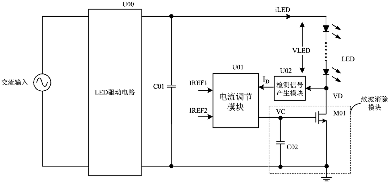
The invention provides a ripple elimination circuit, a ripple elimination method and an LED control circuit applying the ripple elimination circuit. The ripple elimination method comprises the following steps that: the ripple elimination circuit obtains a detection signal representing the voltage at a low potential end of a load, and when the detection signal is less than a first threshold value,load current decreases; when the detection signal is greater than a second threshold value, the load current increases; and when the detection signal is greater than or equal to the first threshold and less than or equal to the second threshold, the load current remains unchanged. The ripple elimination effect is remarkable, and the load current is more stable.

Description

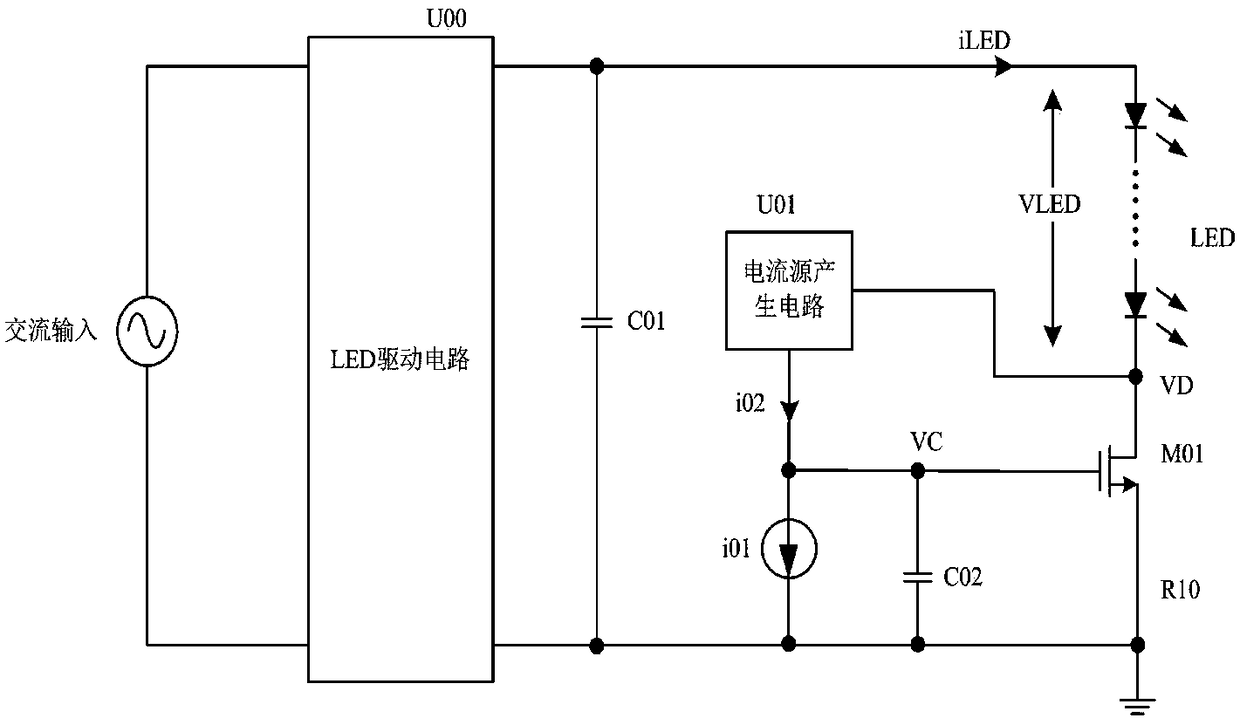
technical field [0001] The invention relates to the field of power electronics, in particular to a ripple elimination circuit, a ripple elimination method and an LED control circuit using the same. Background technique [0002] At present, many AC-DC conversion circuits convert the AC grid input into DC power output with sinusoidal ripples through the LED drive circuit, and the LEDs will have ripples, which will cause damage to human eyes. figure 1 The ripple elimination circuit shown is to filter the ripple on the LED, set the reference voltage Vreg, pull up VC when VD>Vreg, and pull down VC when VD<Vreg, you can adjust the pull-up current i02, i01 and capacitor C02 The size to realize the control of the LED ripple. [0003] Because the actual power grid will fluctuate, the voltages of VD and VC in the prior art will also fluctuate, causing the current of the LED to fluctuate and causing discomfort to human eyes. The prior art cannot solve this technical problem. Cont...

Claims


Application Information

Patent Timeline
Patent Type & Authority Applications(China)
IPC IPC(8): H05B33/08H02M1/15H05B44/00
CPCH02M1/15H05B45/37
Inventor 马恒飞黄必亮周逊伟
Owner JOULWATT TECH INC LTD
Why Eureka
Eureka Blog
Learn More