Household optical fiber wiring box

A wiring box and optical fiber technology, applied in the field of wiring boxes, can solve the problems of easy entry of dust, insects or mice, damage to the integrated wiring box, affecting router signals, etc. The effect of the signal effect

Pending Publication Date: 2018-09-07
江苏欣佰建设集团有限公司
View PDF14 Cites 0 Cited by
  • Summary
  • Abstract
  • Description
  • Claims
  • Application Information

AI Technical Summary

Problems solved by technology

[0002] The inside of the traditional household fiber-to-the-home information wiring box is a bare cavity, which is used to place routers, modems and other equipment. When multiple routers or modems are placed, because there is no designated location, they will be placed in a disorderly manner and cannot be well placed. Cavities for placement are allocated, and after optical fibers are inserted into routers and other equipment, they will also cross vertically and horizontally, appearing disorganized
[0003] In addition, there will be multiple knockout holes on the side of the wiring box for the optical fiber to pass through. When a certain knockout hole is needed, the baffle in the knockout hole needs to be knocked off to use it. However, when the knockout hole is no longer needed, If the original baffle cannot be installed back, the knockout hole will always be open, and it is easy for dust, insects or mice to enter, causing damage to the inside of the integrated wiring box
[0004] In addition, when the wiring box is in normal use, the box cover will be closed, and the antenna of the router placed in the wiring box will be closed in the wiring box, which will greatly affect the signal of the router.

Method used


Image

  • Household optical fiber wiring box
  • Household optical fiber wiring box
  • Household optical fiber wiring box

Examples


Embodiment Construction

[0018] The present invention will be described in further detail below in conjunction with the accompanying drawings.

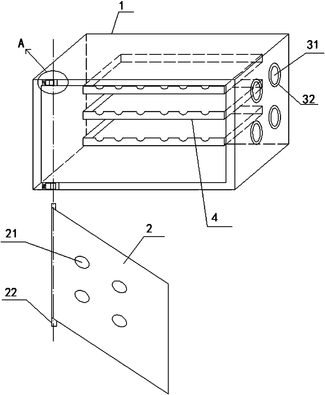
[0019] Such as Figure 1-6 As shown, a household optical fiber wiring box includes a wiring box body 1 and a box cover 2 arranged on the wiring box body 1. The side of the wiring box body 1 is provided with a plurality of perforations 31 for optical fibers to pass through, and each perforation 31 is equipped with A hole cover set 32 ​​is provided, and the hole cover set 32 ​​can close or open the perforation 31 .

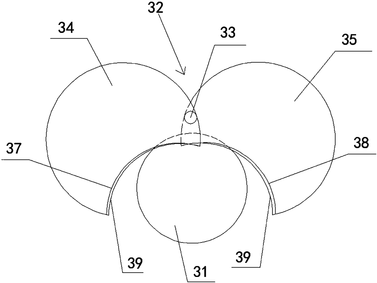
[0020] The hole cover group 32 includes a first rotating shaft 33, a first hole cover 34 and a second hole cover 35. The first rotating shaft 33 is fixedly installed on the outer wall of the wiring box body 1 near the edge of the perforation 31. The first hole cover 34 and the second hole cover The side edges of 35 are respectively arranged on the first rotating shaft 33, the first hole cover 34 can rotate to the left around the first rotating sha...


PUM


Abstract

The invention discloses a household optical fiber wiring box. The household optical fiber wiring box comprises a wiring box body and a box cover arranged on the wiring box body; a plurality of throughholes for optical fibers to penetrate through are formed in the side surface of the wiring box body, each through hole is provided with a hole cover set, and each hole cover set comprises a first rotating shaft, a first hole cover and a second hole cover; placement racks are sequentially horizontally arranged in the wiring box body in the vertical direction, and each placement rack comprises a bottom plate and a side plate vertically arranged at the peripheral edge of the bottom plate; the box cover is detachably arranged on the wiring box body, and an antenna hole for an antenna to penetrateout of is formed in the surface of the box cover. In this way, the household optical fiber wiring box can prevent the situation that dust, insects or rats or the like enter the optical fiber wiring box and cause damage, the placement of the optical fibers can be regulated, the disordered phenomenon is prevented, the box is convenient to manage, and the antenna can conveniently penetrate out of the antenna hole and be covered with the box cover at the same time.

Description

technical field [0001] The invention relates to a wiring box, in particular to a household optical fiber wiring box. Background technique [0002] The inside of the traditional household fiber-to-the-home information wiring box is a bare cavity, which is used to place routers, modems and other equipment. When multiple routers or modems are placed, because there is no designated location, they will be placed in a disorderly manner and cannot be well placed. Cavities for placement are allocated, and after optical fibers are inserted into devices such as routers, they will also cross vertically and horizontally, appearing disorganized. [0003] In addition, there will be multiple knockout holes on the side of the wiring box for the optical fiber to pass through. When a certain knockout hole is needed, the baffle in the knockout hole needs to be knocked off to use it. However, when the knockout hole is no longer needed, If the original baffle cannot be installed back, the knock...

Claims


Application Information

Patent Timeline
Patent Type & Authority Applications(China)
IPC IPC(8): G02B6/44
CPCG02B6/4444G02B6/4446G02B6/44775
Inventor 任栩岑
Owner 江苏欣佰建设集团有限公司
Why Eureka
Try Eureka