


Quick Research
Generate reliable direction feasibility study reports for your R&D in just a few steps.

Technical Q&A
Discover and master advanced knowledge NOW. Basics, ideas, possibilities, all at once.

Find Solutions
As an expert in R&D theories, this can generate solutions to your technical problems instantly.

Evaluate Feasibility
Analyze your overall solution with one click, know your potential R&D risks in advance.

Monitor Landscape
Get weekly tech updates, stay abreast of the latest tech innovations and key insights.
Simple and convenient vertical bent arm flange connection equipment dismounting and mounting device
A connection equipment, vertical technology, applied in the field of disassembly and assembly devices, can solve the problems of inconvenient, high cost, time-consuming and laborious disassembly and assembly, and achieve the effect of convenient disassembly and assembly, low cost and high efficiency
- Summary
- Abstract
- Description
- Claims
- Application Information
AI Technical Summary
Problems solved by technology
Method used
Image

Examples
Embodiment 1
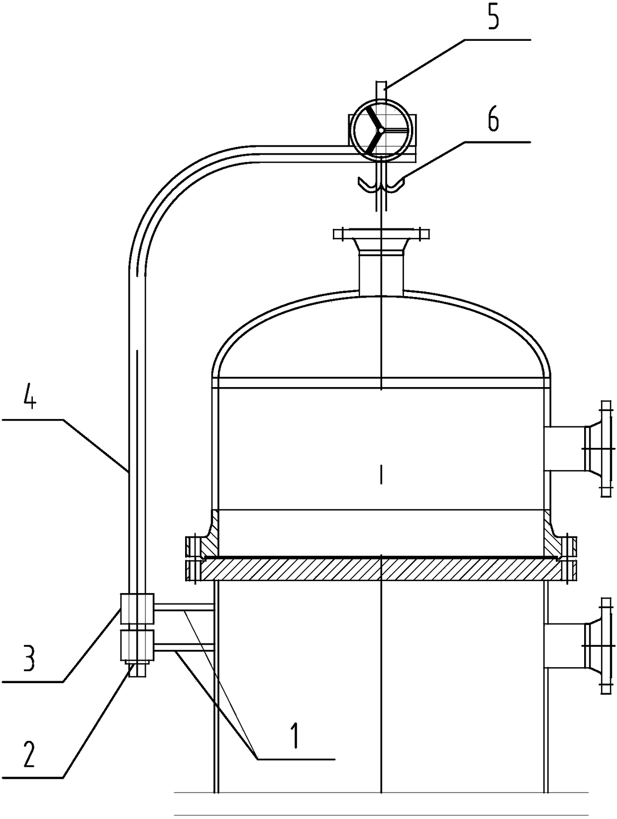
[0019] Such as figure 1 Shown: The flange connection equipment is a new vertical heat exchanger, which includes two parts, the shell side and the tube box. The tube box is on the top, and the shell side is on the bottom. Two bushings 3 are installed, and the two bushings 3 are respectively welded on the shell side cylinder through the connecting plate 1. The lower bushing 3 is provided with a lock nut 2, and the horizontal part of the boom 4 is provided with a vertical Worm screw screw lifter 5, suspension hook 6 is installed in its lifting screw mandrel lower end.
[0020] The new vertical heat exchanger of this embodiment is disassembled and then reassembled for on-site inspection and maintenance as follows:
[0021] Disassembly and assembly of the upper pipe box
[0022] ① Weld the connecting plate 1 to the shell side of the heat exchanger, and connect the hook 6 and the flange (or lifting lug) with a wire rope.
[0023] ②Remove the bolts connecting the pipe box flange a...
Embodiment 2
[0028] The flange connection equipment is an old vertical heat exchanger, and its shell-side cylinder is allowed to be welded. Others are the same as in Embodiment 1.
[0029] The on-site maintenance of this embodiment is completely the same as that of Embodiment 1 when it is first dismantled and then reassembled.
Embodiment 3
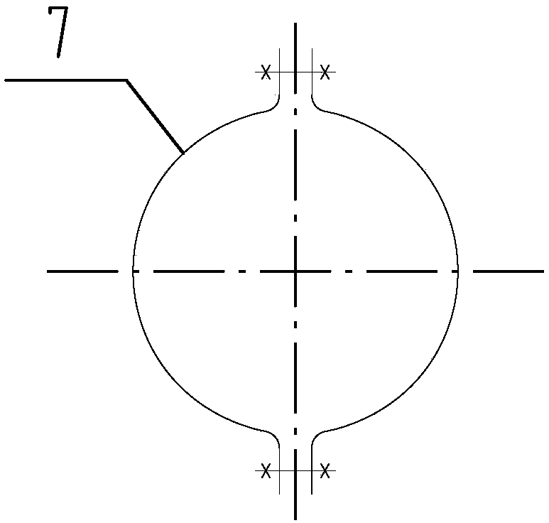
[0031] The flange connection equipment is an old vertical heat exchanger, and its shell-side cylinder is not allowed to be welded. Others are the same as in Embodiment 1.
[0032] In this embodiment, when on-site maintenance is first dismantled and then reassembled, if figure 2 As shown, first a clamp 7 is prefabricated and the clamp 7 is fastened on the shell side cylinder, and then the connecting plate 1 is welded to the clamp 7, and the rest is completely the same as that of the first embodiment.
PUM
 Abstract
Description
Claims
Application Information
 - R&D Engineer
- R&D Manager
- IP Professional
- Industry Leading Data Capabilities
- Powerful AI technology
- Patent DNA Extraction
Browse by: Latest US Patents, China's latest patents, Technical Efficacy Thesaurus, Application Domain, Technology Topic, Popular Technical Reports.
© 2024 PatSnap. All rights reserved.Legal|Privacy policy|Modern Slavery Act Transparency Statement|Sitemap|About US| Contact US: help@patsnap.com