Multi-axial fatigue life prediction model

A fatigue life prediction and model technology, applied in special data processing applications, instruments, electrical digital data processing, etc., can solve the problems that various materials cannot be widely used, and the impact cannot be fully considered, so as to achieve wide material adaptability and wide material Applicability, high-precision effect

Inactive Publication Date: 2018-09-04
NORTHEASTERN UNIV
View PDF7 Cites 7 Cited by
  • Summary
  • Abstract
  • Description
  • Claims
  • Application Information

AI Technical Summary

Problems solved by technology

[0005] Aiming at the shortcomings that the existing critical plane model cannot comprehensively consider the influence of additional strengthening phenomena on the multiaxial fatigue life, and cannot be widely used in various materials, the problem to be solved by the present invention is to provide a material with higher precision and wider range An Adaptive Multiaxial Fatigue Life Prediction Model

Method used


Image

  • Multi-axial fatigue life prediction model
  • Multi-axial fatigue life prediction model
  • Multi-axial fatigue life prediction model

Examples


Embodiment Construction

[0041] The present invention will be further elaborated below in conjunction with the accompanying drawings of the description.

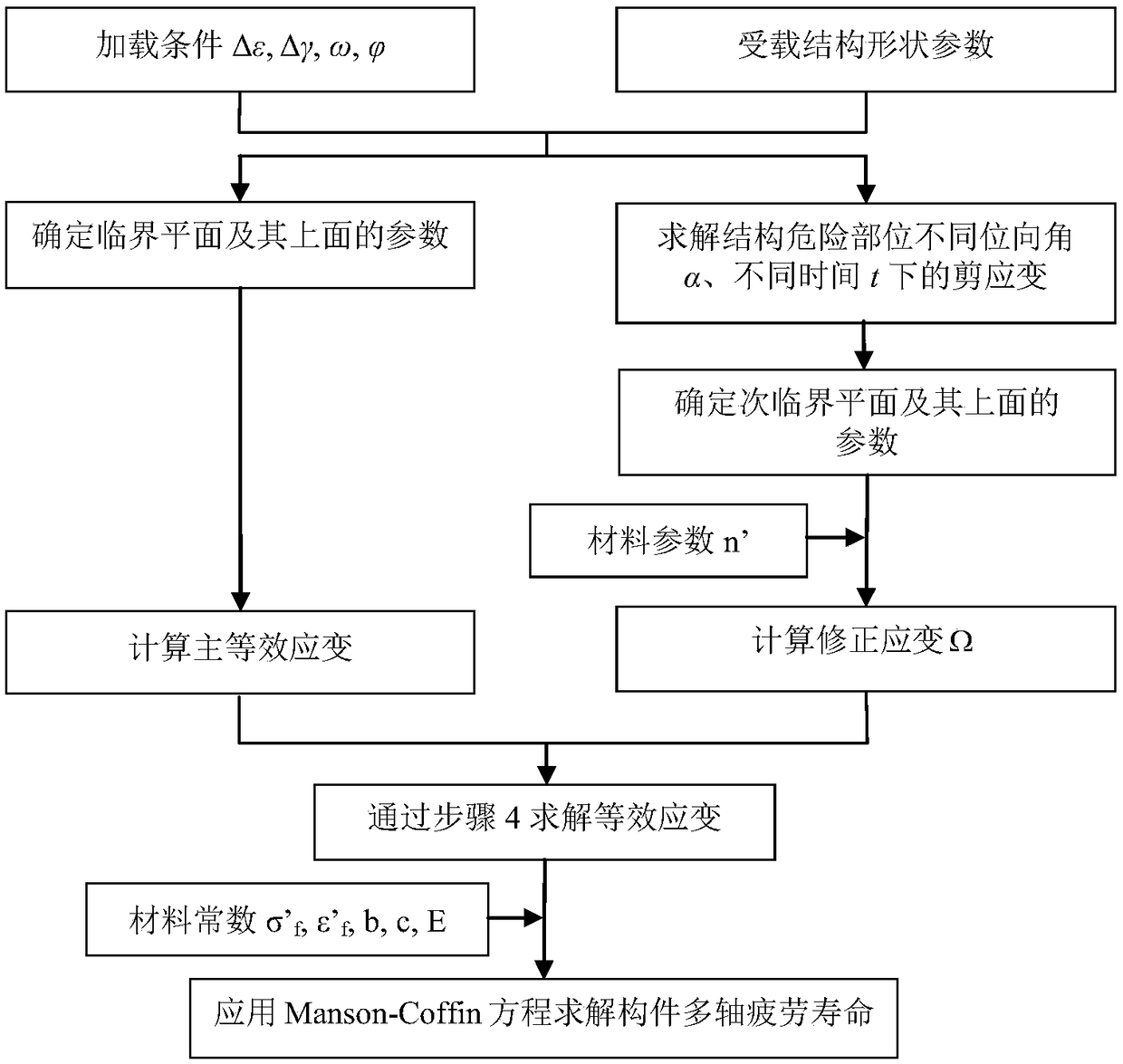
[0042] Such as image 3 Shown, a kind of multiaxial fatigue life prediction method of the present invention comprises the following steps:

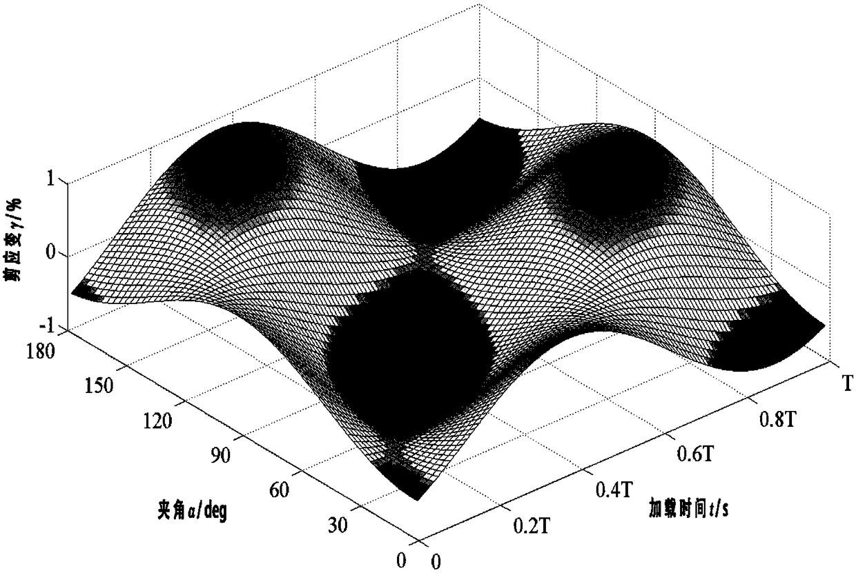
[0043] 1) Using finite element analysis to solve the shear strain of the dangerous part of the thin-walled member at different orientation angles α and at different times t, and obtain the change history diagram of the shear strain of the dangerous part of the thin-walled member;

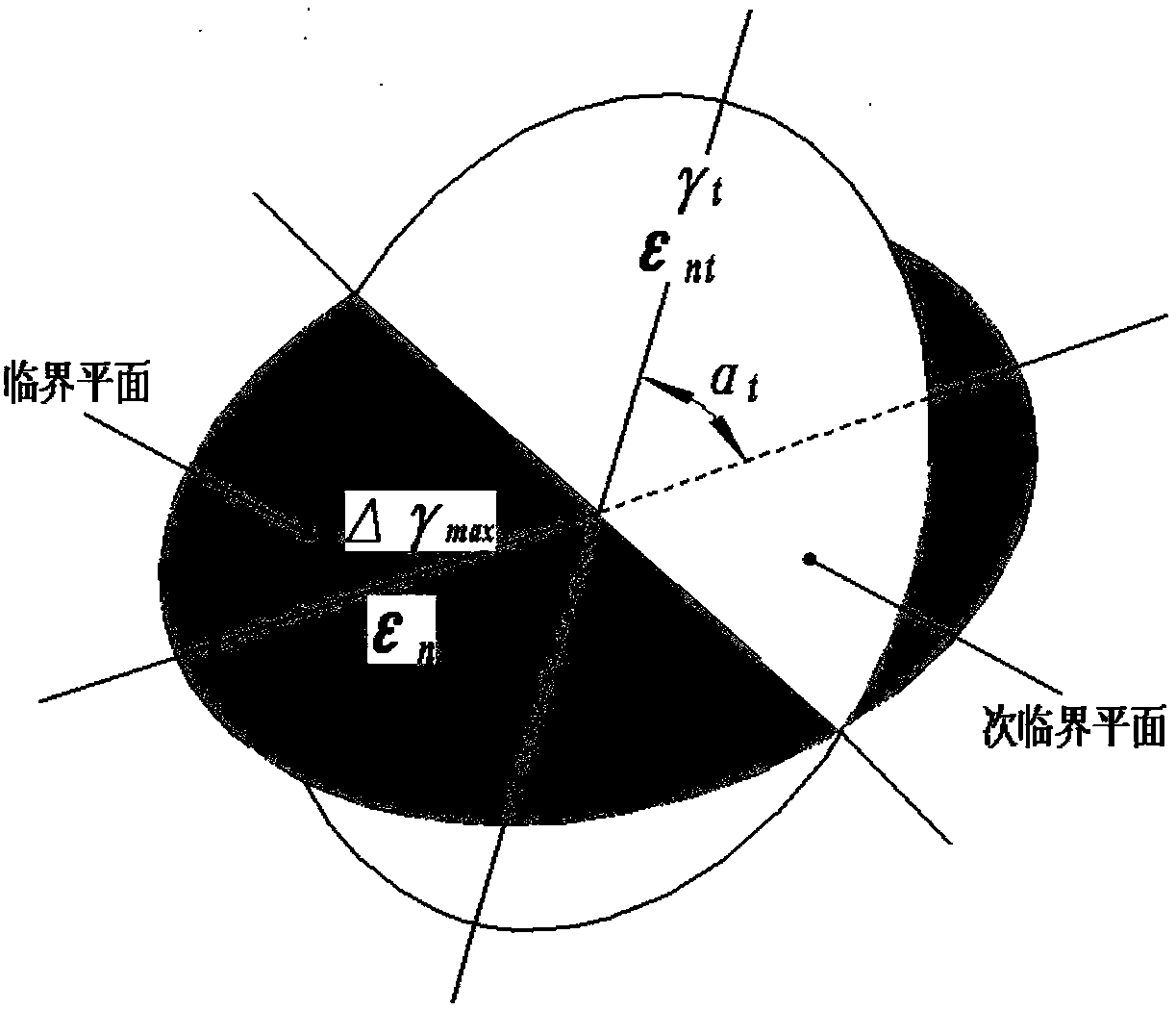
[0044] 2) Through the above change history diagram, the plane where the maximum shear strain amplitude is located is obtained, and this plane is defined as the main critical plane, and the orientation angle of this plane is defined as α max ;

[0045] 3) Define any time t, and obtain the plane where the maximum shear strain is located at this time through the above-mentioned change history diagram, define this plane as the subcriti...


PUM


Abstract

The invention relates to a multi-axial fatigue life prediction model. The model is implemented through the following steps of: solving shearing strains, at different orientation angles <alpha> and different moments t, at a danger part of a thin-wall component, so as to obtain a change process diagram of the shearing strains at the dangerous part of the thin-wall component; enabling the orientationangles to be <alpha>max and <alpha>t through the change process diagram, a primary critical plane and a secondary critical plane; calculating an average additional reinforcement influence factor in aloading period on the secondary critical plane; solving a main equivalent strain on the primary critical planes by combining strain parameters on the primary critical plane; synthesizing a parametersolved on the primary critical plane and a parameter solved on the secondary critical plane into an equivalent strain, wherein the parameter solved on the primary plane is the main equivalent strain and the parameter solved on the secondary critical plane is a correction strain; and combining the equivalent strain with a Manson-Coffin equation to solve multi-axial fatigue life of the structure. Starting with a principle of generating additional reinforcement in a multi-axial loading process, the invention discloses a novel multi-axial fatigue life prediction model which is has higher precisionand wider material adaptation.

Description

technical field [0001] The invention relates to a life prediction model of mechanical components, in particular to a multi-axis fatigue life prediction model. Background technique [0002] In engineering practice, most engineering structures and mechanical parts are subjected to various forms of cyclic loads, and the load distribution mostly presents a multiaxial stress state. Even in a uniaxial external load environment, in view of the complexity of the geometry of the component, the actual load on its dangerous parts is still multi-axially distributed, and the failure mode also belongs to multi-axial fatigue failure. Therefore, under cyclic loading, the research on multiaxial fatigue is closer to engineering practice than uniaxial fatigue, and has a wider application background. [0003] The earliest multiaxial fatigue estimation methods usually equate multiaxial fatigue damage to uniaxial conditions, and then study the fatigue life prediction method under multiaxial load...

Claims


Application Information

Patent Timeline
IPC IPC(8): G06F17/50
CPCG06F30/17G06F30/23
Inventor 赵丙峰谢里阳樊富友胡杰鑫张诗健李海洋李冲
Owner NORTHEASTERN UNIV
Why Eureka
Try Eureka