
Sample collection device, system, method and storage medium

A technology for sample collection and sample storage, applied in sampling devices and other directions, can solve the problems of long sampling time, influence and change, and achieve the effect of short sampling time and high efficiency

Active Publication Date: 2020-10-09
INST OF PROCESS ENG CHINESE ACAD OF SCI +1
View PDF11 Cites 0 Cited by
  • Summary
  • Abstract
  • Description
  • Claims
  • Application Information

AI Technical Summary

Problems solved by technology

[0004] However, due to the limitation of analytical detection means, the chemical characterization of gaseous products and particulate matter produced during the reaction is different
Among them, the gas products can be detected online or collected and detected at any time during the reaction process, but the collection of particulate matter in the reaction system is limited to the two states before the reaction starts and after the end of the reaction / pause. The results obtained from this It is macroscopic and integral, and cannot reflect the changing trend and law of the particulate matter during the transformation process, so it is impossible to conduct kinetic analysis to reveal the reaction mechanism through the characterization of solid particles, and to regulate the reaction process
In addition, in related technologies, there are problems in the collection of particulate matter such as “sampling pipelines and sampling chambers have sample residues that affect subsequent sample collection”, “collected samples cannot be packaged or their physical and chemical properties change during storage”, “continuous sampling cannot ", "Manual operation causes a waste of manpower and material resources" and "a single sampling takes a long time and the collection efficiency is low" and other defects

Method used


Image

  • Sample collection device, system, method and storage medium
  • Sample collection device, system, method and storage medium
  • Sample collection device, system, method and storage medium

Examples


Embodiment 1

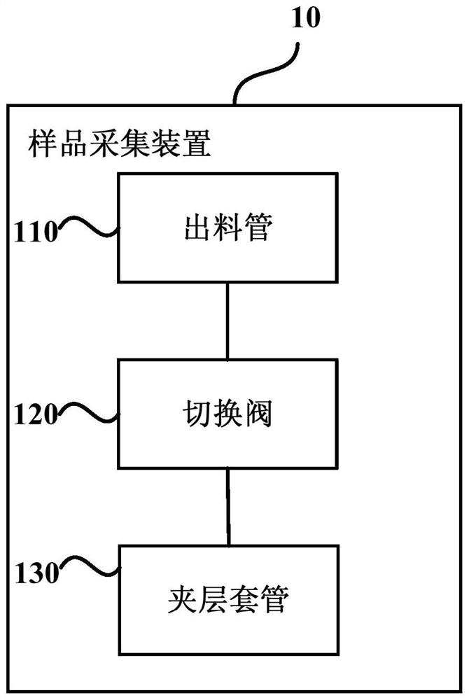
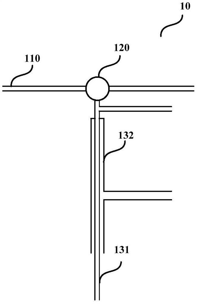
[0034] Figure 1A It is a schematic structural diagram of a sample collection device provided in Embodiment 1 of the present invention, which is applied to particle sample collection. like Figure 1A As shown, the specific sample collection device 10 includes: a discharge pipe 110 , a switching valve 120 and a sandwich sleeve 130 .

[0035] The first port of the discharge pipe 110 is connected to the sample reaction device, and the second port of the discharge pipe 110 is connected to the first port of the switching valve 120 for transferring samples;

[0036] The second port of the switching valve 120 is connected with the inner layer pipeline of the sandwich sleeve 130 for transferring the sample to the sample storage device; the third port of the switching valve 120 is connected with the purging device for cleaning after the sampling is finished. Purge sample reaction device and sample storage device;

[0037] The outer pipeline of the sandwich casing 130 is connected with...

Embodiment 2

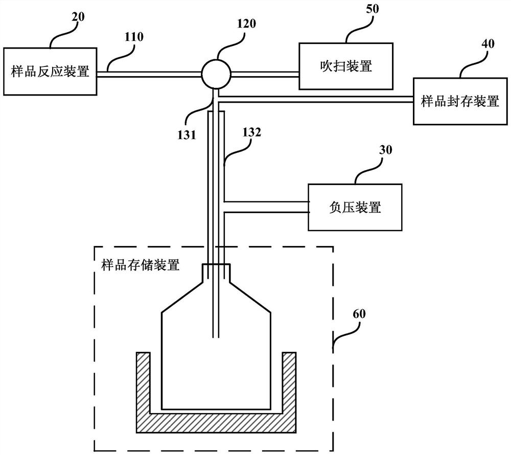
[0048] Figure 2A It is a schematic diagram of a sample collection system provided in Embodiment 2 of the present invention. like Figure 2A As shown, the sample collection system includes: a sample collection device 10, a sample reaction device 20, a negative pressure device 30, a sample sealing device 40, a purging device 50, and a sample storage device 60;

[0049] The sample collection device 10 communicates with the sample reaction device 20 , the negative pressure device 30 , the sample sealing device 40 , the purging device 50 and the sample storage device 60 respectively.

[0050] Figure 2B It is a detailed structural schematic diagram of a sample collection system, providing a detailed structural schematic diagram of a sample reaction device, a negative pressure device, a sample storage device, a purging device and a sample storage device for continuous online collection of solid particle samples. like Figure 2B Shown:

[0051] The sample reaction device includ...

Embodiment 3

[0069] Fig. 3 is a schematic diagram of a sample collection system provided by Embodiment 3 of the present invention, in Figure 2B On the basis of the acquisition system diagram provided, it also includes: gas acquisition on-line detection device, which is used for continuous on-line solid sampling and characterization during the reaction process, and real-time analysis of gas phase components to achieve the purpose of reaction evaluation.

[0070] like Figure 3A As shown, it includes a second filter 710, a fourth valve 720, a shut-off valve 730 and a gas component detector 740 for online detection of gas samples in the reaction process; wherein, the gas component detector 740 and the first stop valve 730 The ports are connected, the second port of the stop valve 730 is connected with the first port of the fourth valve 720, the second port of the fourth valve 720 is connected with the first port of the second filter 710, and the second port of the second filter 710 is connec...


PUM

PropertyMeasurementUnit
diameteraaaaaaaaaa
diameteraaaaaaaaaa

Abstract

The embodiment of the invention discloses a sample collection device, system and method and a storage medium. The sample collection device comprises a discharge pipe, a switching valve and an interlayer sleeve, wherein a first port of the discharge pipe is communicated with a sample reaction device; a second port of the discharge pipe is communicated with a first port of the switching valve; a second port of the switching valve is communicated with an inner pipeline of the interlayer sleeve; a third port of the switching valve is communicated with a purging unit; an outer pipeline of the interlayer sleeve is communicated with a negative-pressure unit; the inner pipeline of the interlayer sleeve is communicated with a sample seal device; and the inner pipeline of the interlayer sleeve is communicated with the sample storage device. The sample collection device can achieve the beneficial effect that particle samples can be automatically and continuously collected, and is low in samplingtime consumption and high in efficiency.

Description

technical field [0001] The embodiments of the present invention relate to the technical field of substance reaction detection, and in particular to a sample collection device, system, method and storage medium. Background technique [0002] In the process of material conversion, the continuous characterization of the reaction process is very important for the study of the reaction mechanism and the process control of the reaction. [0003] Compared with the traditional fixed bed system, the fluidized bed system has the advantages of uniform distribution of reaction material particles and being in the same reaction state. The reactant particles collected online from the fluidized bed system can more accurately reflect the microscopic state of the solid particles in the reaction system. [0004] However, the chemical characterization of the gaseous products and particulate matter produced during the reaction varies due to limitations in analytical detection means. Among them...

Claims


Application Information

Patent Timeline
Patent Type & Authority Patents(China)
IPC IPC(8): G01N1/24
CPCG01N1/24
Inventor 岳君容许光文关宇朱庆凯
Owner INST OF PROCESS ENG CHINESE ACAD OF SCI
Learn More