
Geothermal well underground multi-loop heat exchange method

A multi-loop, thermal method technology, applied in the directions of geothermal energy, geothermal energy power generation, geothermal collectors, etc., can solve the problems of difficult to control the drilling and recovery rate, difficult to control the success rate, low heat exchange efficiency, etc. operability, reducing the risk of geological prediction, and improving the effect of thermal energy utilization

Pending Publication Date: 2018-09-04
HENAN POLYTECHNIC UNIV
View PDF4 Cites 5 Cited by
  • Summary
  • Abstract
  • Description
  • Claims
  • Application Information

AI Technical Summary

Problems solved by technology

[0007] The mining of hot dry rock is mainly to establish an underground heat exchange system, and the above-mentioned artificial high-pressure fracture mode, natural fracture mode, and natural fracture-fault mode require a high degree of understanding of underground geological conditions, high engineering risks, and difficult to control the success rate of drilling and production
Since the heat energy of dry hot rocks is stored in various metamorphic rocks or crystalline rocks with high strength (biotite gneiss, granite, granodiorite, etc.), the cost of artificial fracturing connection is high, and the success rate is difficult to control
In addition, for the geothermal utilization of medium-temperature geothermal reservoirs, the temperature is below 150°C, and this part of geothermal utilization can also be utilized through heat exchange. Usually, single-well concentric double-layer tubes are used for heat exchange, but the heat exchange efficiency is low

Method used


Image

  • Geothermal well underground multi-loop heat exchange method

Examples


Embodiment

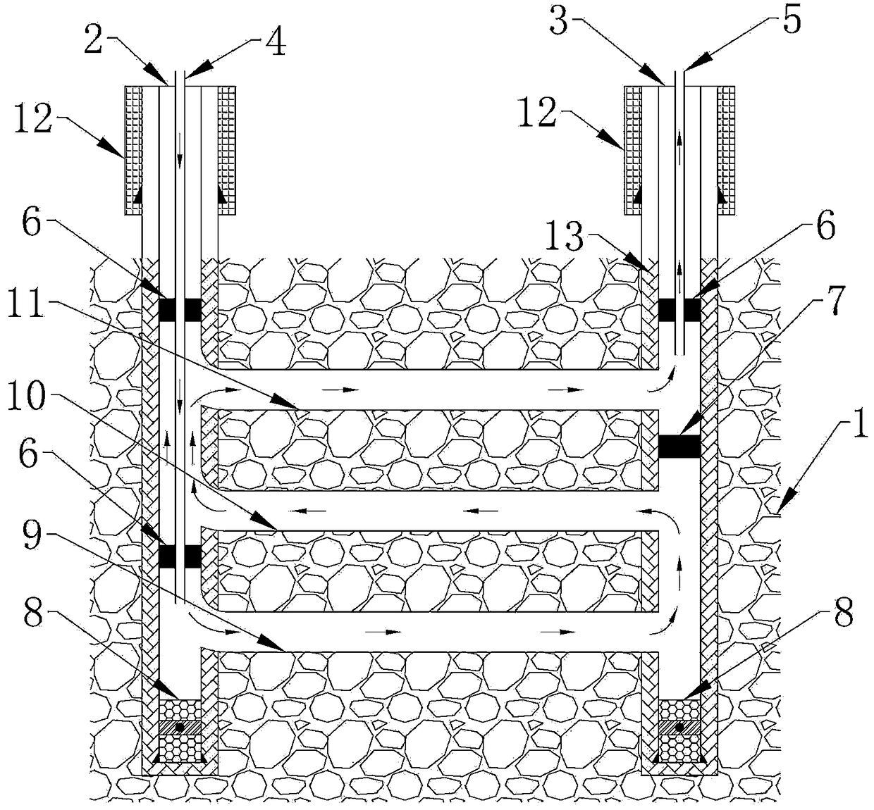
[0027] Such as figure 1 As shown, the present invention is implemented by taking three heat exchange branch wells as an example, a geothermal downhole multi-circuit heat exchange method, the geothermal well includes a water injection well 2, a water production well 3 and a heat exchange branch well, and the multi-circuit heat exchange method Include the following steps:

[0028] Step1. Set up several geological exploration wells in the construction area to collect the formation temperature and lithology information of the geothermal reservoir 1 for underground heat storage;

[0029] Step2. Calculate the distance between the water injection well and the water production well, and the borehole diameter of the horizontal well connecting the water injection well and the water production well according to the lithology information such as temperature, porosity, and rock strength of the dry geothermal reservoir collected in Step1;

[0030] Step3. According to the results of the abo...


PUM


Abstract

Disclosed is a geothermal well underground multi-loop heat exchange method. According to the method, a water injection well, a water production well, and a plurality of heat exchange branch wells aredrilled in a geothermal reservoir, wherein the heat exchange branch wells are horizontal wells enabling the water injection well to communicate with the water production well; the water injection wellis internally provided with a central water injection pipe, a well casing packer and a bottom hole blocking seat; the water production well is internally provided with a central water production pipe, a downhole packer and a bottom hole blocking seat; the central water production pipe is fixed into the water production well by the well casing packer; a serpentine heat exchange loop is formed between the water injection well, the water production well, the heat exchange branch wells, the downhole packer and the well casing packer; and heat exchange of a heat exchange medium and the geothermalreservoir is completed through flowing of the heat exchange medium in the serpentine heat exchange loop. The present invention can reduce the risk of geological prediction, reduces the risk of fracturing, uses a controllable engineering construction method to achieve heat exchange purposes, proposes a fixed-point injection mode to control heat exchange efficiency, increases engineering operability, and increases thermal energy utilization of geothermal reservoirs.

Description

technical field [0001] The invention relates to the technical field of adopting underground heat energy by geothermal wells, in particular to a multi-circuit heat exchange method for underground geothermal wells. Background technique [0002] Hot dry rock refers to underground high-temperature rock mass with a buried depth of more than 2000m and a temperature of more than 150°C. It is characterized by the fact that there are few underground fluids in the rock mass. The heat energy of hot dry rocks is stored in various metamorphic rocks or crystalline rocks. The more common hot dry rocks include biotite gneiss, granite, and granodiorite. The existence of an underground high-temperature rock mass with a temperature exceeding 150 °C will definitely bring great abnormalities to the surrounding geothermal environment, so many researchers also use whether the geothermal gradient is super-abnormal to study whether there is a dry hot rock mass underground. [0003] At present, peop...

Claims


Application Information

Patent Timeline
Patent Type & Authority Applications(China)
IPC IPC(8): F24T10/15E21B43/30
CPCE21B43/305Y02E10/10
Inventor 鲜保安毕延森傅绎琳张晓斌王鹏涛张洲田林
Owner HENAN POLYTECHNIC UNIV
Learn More