
Expansion joint dust collecting device and construction method thereof

A dust collection device and construction method technology, applied in the direction of pollution prevention methods, chemical instruments and methods, cleaning methods and appliances, etc., can solve problems such as polluted air, hidden safety hazards, and hard connection failures, so as to avoid air pollution and improve Safety, the effect of avoiding potential safety hazards

Active Publication Date: 2018-09-04
安徽谦源项目管理有限公司
View PDF6 Cites 11 Cited by
  • Summary
  • Abstract
  • Description
  • Claims
  • Application Information

AI Technical Summary

Problems solved by technology

The existing expansion joint structures are equipped with cover plates, and the cover plates are usually steel plates that fit together. Since the steel plates that fit together are hard links, in order to avoid the hard connection failure caused by thermal expansion and contraction, the existing technology Usually, a gap is set on the cover plate of the expansion joint, and the gap on the cover plate is used to make the cover plate have a certain fit margin to meet the requirements of thermal expansion and contraction. However, the existence of the gap will inevitably lead to fine sand, dust and other impurities. Objects fall from the cover of the expansion joint and fall directly under the bridge
These falling fine sand, dust and other debris not only pollute the air, but also pose certain safety hazards
In the prior art, there is no technical means to effectively intercept the fine sand, dust and other debris leaked from the expansion joint cover plate, resulting in the inability to effectively collect the sand, dust and other sundries leaked from the expansion joint

Method used


Image

  • Expansion joint dust collecting device and construction method thereof
  • Expansion joint dust collecting device and construction method thereof
  • Expansion joint dust collecting device and construction method thereof

Examples


Embodiment Construction

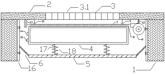
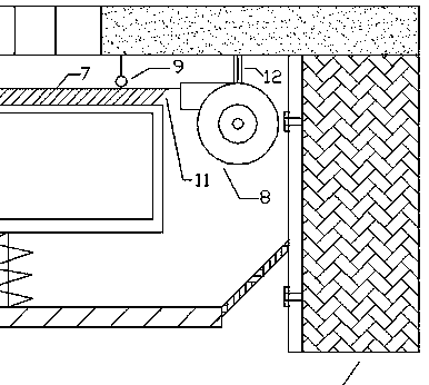
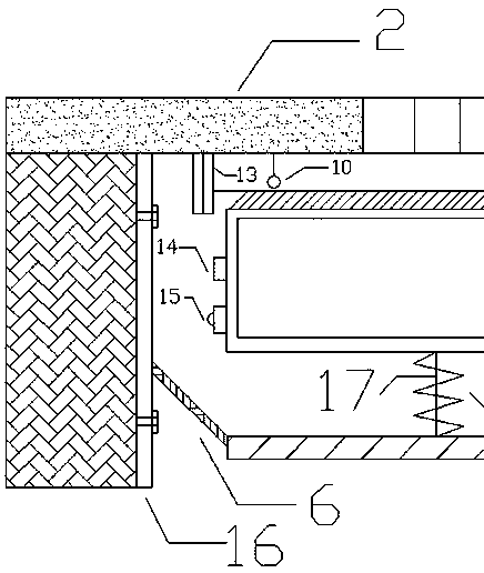
[0020] The present invention will be further described below in conjunction with the accompanying drawings. See attached figure 1 - 5. The expansion joint dust collection device of the present invention includes the main body 1 of the bridge, the bridge surface 2, the expansion joint cover plate 3, the dust collection box 4 and the dust receiving plate 7. Among them, the bridge main body 1 refers to the bridge structure on both sides of the expansion joint, and an expansion joint is set between the two bridge main bodies 1. figure 1 It can be seen that the expansion joint is set flush with the bridge surface 2 of the bridge, and then the expansion joint cover plate 3 is installed on the expansion joint. On the one hand, the expansion joint cover plate 3 covers the expansion joint, so that vehicles, etc. can pass through the expansion joint On the one hand, by setting the expansion joint cover plate 3 to make the expansion joint have a certain thermal expansion and contraction...


PUM


Abstract

The invention relates to an expansion joint dust collecting device and a construction method thereof. The expansion joint dust collecting device comprises a bridge body, a bridge deck and an expansionjoint cover plate and is characterized in that a dust collecting box is arranged below the expansion joint cover plate, a dust receiving plate is arranged at the top of the dust collecting box, and tiny gravels, dust and other sundries fall downwardly through the gaps of the expansion joint cover plate onto the dust receiving plate and are guided into the dust collecting box through the dust receiving plate; when the dust quantity in the dust collecting box reaches a preset value, an alarm lamp flickers to give out an alarm to remind maintenance staff to clean the dust collecting box. The expansion joint dust collecting device has the advantages that by arranging the dust collecting box below the expansion joint cover plate, the fallen tiny gravels, dust and other sundries can be completely collected in the dust collecting box, atmospheric pollution is avoided, risks caused by the fact that the tiny gravels, dust and other sundries fall off the bridge deck, and bridge safety is increased.

Description

technical field [0001] The invention relates to the fields of bridge construction and water conservancy construction, in particular to an expansion joint dust collecting device and a construction method thereof. Background technique [0002] Existing bridges are provided with expansion joint structures at bridge deck joints, and the expansion joint structures are used to ensure that the bridge has good thermal expansion and contraction performance. The existing expansion joint structures are equipped with cover plates, and the cover plates are usually steel plates that fit together. Since the steel plates that fit together are hard links, in order to avoid the hard connection failure caused by thermal expansion and contraction, the existing technology Usually, a gap is set on the cover plate of the expansion joint, and the gap on the cover plate is used to make the cover plate have a certain fit margin to meet the requirements of thermal expansion and contraction. However, t...

Claims


Application Information

Patent Timeline
IPC IPC(8): E01D19/06B08B17/02
CPCB08B17/02E01D19/06
Inventor 王涛
Owner 安徽谦源项目管理有限公司
Learn More