Sludge dewatering machine for environment protection

A sludge dewatering machine and environmental protection technology, which is applied in the direction of water/sludge/sewage treatment, sludge treatment, dehydration/drying/concentrated sludge treatment, etc., can solve the inconvenience of sewage volume, sewage clogging in the machine, machine Damage and other problems, to prevent excessive inflow and easy blockage, reduce shaking, and improve service life

Inactive Publication Date: 2018-09-04
杨琼
View PDF0 Cites 2 Cited by
  • Summary
  • Abstract
  • Description
  • Claims
  • Application Information

AI Technical Summary

Problems solved by technology

[0005] Aiming at the deficiencies of the prior art, the present invention provides a sludge dehydrator for environmental protection, which has the advantages of not being easily blocked and easy to adjust, and solves the problem that the existing sludge dewaterer is inconvenient to control the amount of sewage flowing in, which may cause Too much sewage flowing in will easily cause sewage to block the machine, and too little sewage flowing into the sludge dewatering machine will easily cause damage to the machine. Some existing dehydrating machines are at the filter screen, which is likely to cause a small amount of sludge Accumulated on the top, prone to clogging

Method used


Image

  • Sludge dewatering machine for environment protection
  • Sludge dewatering machine for environment protection
  • Sludge dewatering machine for environment protection

Examples


Embodiment Construction

[0026] The following will clearly and completely describe the technical solutions in the embodiments of the present invention with reference to the accompanying drawings in the embodiments of the present invention. Obviously, the described embodiments are only some, not all, embodiments of the present invention. Based on the embodiments of the present invention, all other embodiments obtained by persons of ordinary skill in the art without making creative efforts belong to the protection scope of the present invention.

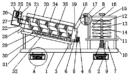
[0027] see Figure 1-4, a sludge dehydrator for environmental protection, comprising a support plate 1, a vertical column 31 is fixedly installed on the top of the support plate 1, the vertical column 31 is located on the left side of the vertical bar 3, the length of the vertical column 31 is greater than the length of the vertical bar 3, The top of vertical bar 3 is fixedly connected with separation box 20, and the right side of separation box 20 is fixedly ...


PUM


Abstract

The invention relates to the technical field of environment protection equipment, and discloses a sludge dewatering machine for environment protection. The sludge dewatering machine comprises a supporting plate, a buffering device is fixedly mounted at the bottom of the supporting plate, a vertical rod is fixedly mounted at the top of the supporting plate, two supporting rods are fixedly mounted at the top of the supporting plate, the supporting rods are located on the right side of the vertical rod, the top ends of the supporting rods are fixedly connected with a stirring box, and the top ends of the two supporting rods are fixedly connected with the two sides of the bottom of the stirring box. The sludge dewatering machine for environment protection rotates a rotating disc to drive a movable clamping plate to rotate through cooperation among the rotating disc, a fixing disc, a limiting hole, a positioning hole and a clamping rod in an adjusting device, accordingly the flowing cross area of the sludge in the stirring box is limited through the coincidence area between the movable clamping plate and a fixed clamping plate, therefore the speed of the sludge entering a separation boxis controlled conveniently, and thus the situation that the machine is prone to being blocked due to too much sludge flows, and the machine can be damaged due to too less sludge flows can be prevented.

Description

technical field [0001] The invention relates to the technical field of environmental protection equipment, in particular to a sludge dehydrator for environmental protection. Background technique [0002] Sludge is an inevitable product of sewage treatment in sewage treatment plants and sewage stations. Untreated sludge entering the environment will directly bring secondary pollution to water bodies and the atmosphere, and it will also affect the ecological environment and human activities. would pose a serious threat. Therefore, sludge treatment is very cautious. Sludge treatment can be divided into sludge dehydration process and sludge drying process. The following mainly introduces the respective advantages of different types of sludge dewatering machines. Sludge dehydration The machine is a kind of sludge treatment equipment with continuous operation. It is loved by the public because of its low water content in sludge, stable operation, low energy consumption, relativel...

Claims


Application Information

Patent Timeline
Patent Type & Authority Applications(China)
IPC IPC(8): C02F11/12
CPCC02F11/121
Inventor 张孝法
Owner 杨琼
Why Eureka
Try Eureka