Pneumatically controlled drain valve

A technology of drain valve and check valve, which is applied in the direction of steam trap, valve device, valve details, etc., and can solve problems such as adverse effect on compressor function, damage to membrane, loss of compressor transmission power, etc.

Active Publication Date: 2020-02-18
KNORR BREMSE SYST FUR SCHIENENFAHRZEUGE GMBH
View PDF5 Cites 0 Cited by
  • Summary
  • Abstract
  • Description
  • Claims
  • Application Information

AI Technical Summary

Problems solved by technology

Known pneumatically controlled drain valves (as described above and in figure 1 Drain valve shown as an example in ) does not adequately drain the cooler after the compressor has been shut down
In addition, the displacement is also limited by the filling volume of the valve.
As a result, condensate accumulates in the cooler chamber, which condensate adversely affects the function of the compressor
The functional reliability of such valves is also limited by condensation accumulating on the membrane, since aggressive condensation damages the membrane and shortens its service life
If the membrane no longer seals reliably due to damage, compressed air and condensate can flow into the hood and thus in particular also to the outside, even with the inlet valve closed, whereby the compressor significantly loses delivery power

Method used


Image

  • Pneumatically controlled drain valve
  • Pneumatically controlled drain valve
  • Pneumatically controlled drain valve

Examples


Embodiment Construction

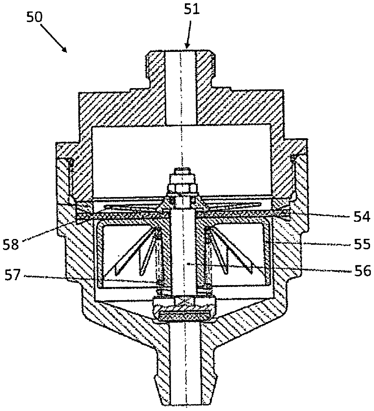
[0026] figure 1 The already described drain valve 50 known from the prior art is shown in the use position in which the connection port 51 is connected to the cooler of an air compressor (not shown). The drain valve 50 has an air bellows 55 which, during compressor operation, is pressed downwards against the force of a spring 57 by the pressure of the air-condensate mixture flowing in via the connection opening 51 . As a result, the inlet valve 58 arranged centrally on the drain valve 50 is opened in order to allow compressed air and condensate to flow into the hood below the membrane 54 . In this case, the valve piston 56 arranged in the lower region seals against the discharge opening of the drain valve 50 . Once the pressure is equalized in the chambers provided above and below the gas shield 55, the gas shield 55 moves upwards due to the upwardly directed force of the spring 57 and closes the inlet valve 58. The pressure in the chamber above the membrane 54 finally drops...


PUM


Abstract

The invention relates to a drain valve for a cooler of a compressor, comprising a pressure chamber which can be connected to the interior of the cooler via a connection port and which has a drain for draining condensate. The proposed valve has a pneumatic switching device and a non-return valve, which are operatively connected to the pressure chamber, wherein there is an operative connection between the switching device and the non-return valve, by means of which the non-return valve can be switched from the switching device actuation to open position. When the compressor is not in operation, the non-return valve can be actuated into an open position by means of the switching device, so that condensate can be drained from the connection via the non-return valve through the discharge port.

Description

technical field [0001] The invention relates to a drain valve for a cooler of a compressor, comprising a pressure chamber connectable to the inner space of the cooler via a connection port and a drain for draining condensate. The valve has a pneumatic switching device and a non-return valve, which are operatively connected to the pressure chamber. Background technique [0002] Pneumatically controlled drain valves are known in the prior art, as exemplified in figure 1 as shown in the position of use. In this valve, a gas shield is pressed downwards against the force of a spring during compressor operation, thereby opening an inlet valve arranged approximately centrally in the drain valve so that compressed air and condensate can flow into the chamber below the membrane. In the bell chamber (Glockenraum, bell-shaped chamber), at the same time, the valve piston is arranged in cooperation with the discharge opening provided at the lower part to close the valve. The inlet val...

Claims


Application Information

Patent Timeline
Patent Type & Authority Patents(China)
IPC IPC(8): F04B39/16F04B53/04F04B53/10F16T1/14
CPCF04B39/16F04B53/04F04B53/1027F04B53/1032F16T1/14F16K21/00F04B53/1022F16K31/1221
Inventor T·基普E·阿夫沙A·弗里克
Owner KNORR BREMSE SYST FUR SCHIENENFAHRZEUGE GMBH
Why Eureka
Try Eureka