
Spar conveying method

A spar, feeding technology, applied in the field of spar feeding, to achieve the effect of continuous orientation and feeding

Inactive Publication Date: 2018-08-28
ZHEJIANG HEHE ELECTROMECHANICAL CO LTD
View PDF8 Cites 1 Cited by
  • Summary
  • Abstract
  • Description
  • Claims
  • Application Information

AI Technical Summary

Problems solved by technology

However, most of the existing spars are manually loaded or picked up by manipulators on the corresponding discs. During the use of spars, it is often necessary to accurately, continuously and stably transport a specific number of spars, and the existing equipment cannot meet this requirement. need

Method used


Image

  • Spar conveying method
  • Spar conveying method
  • Spar conveying method

Examples


Embodiment Construction

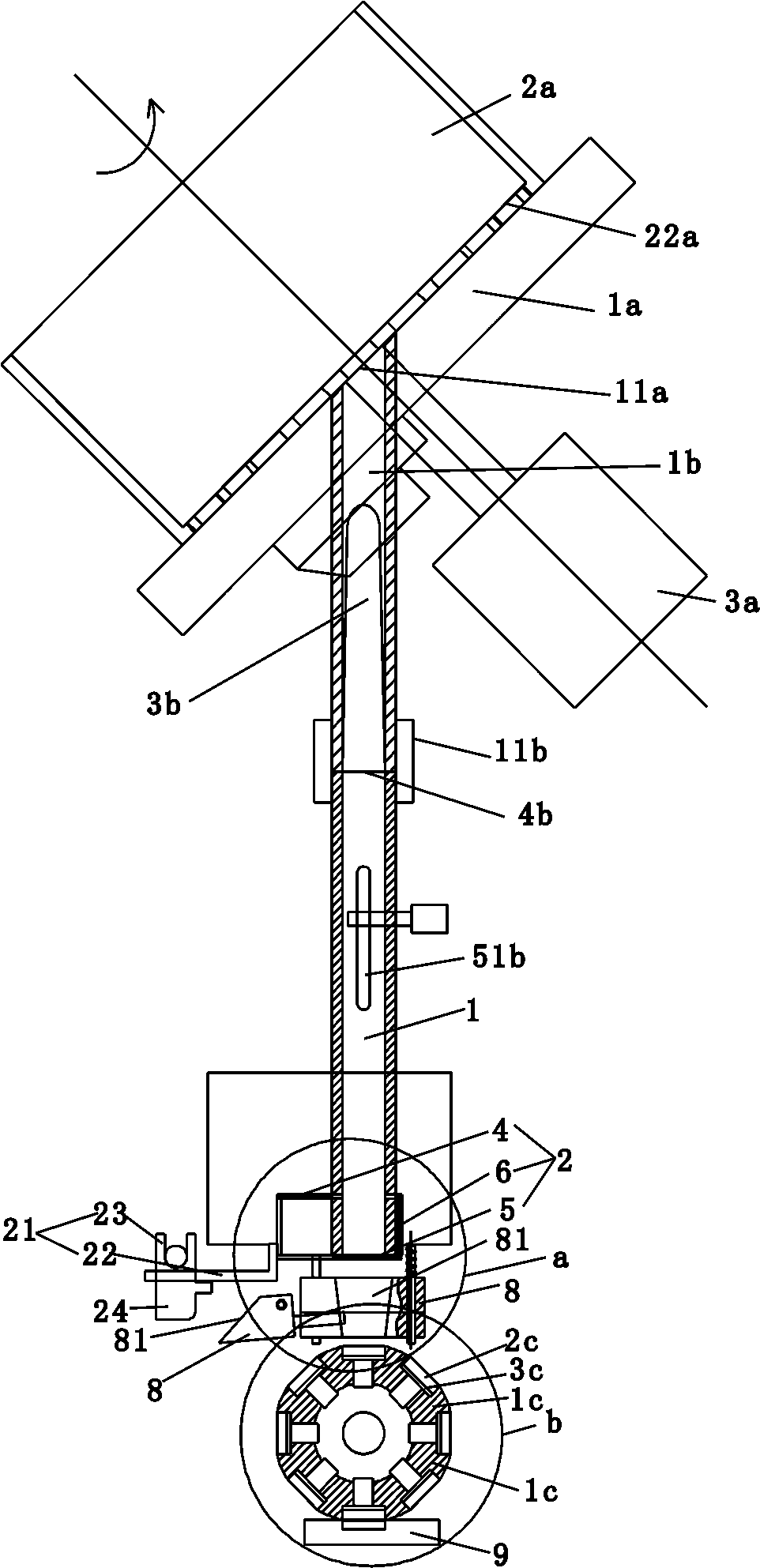
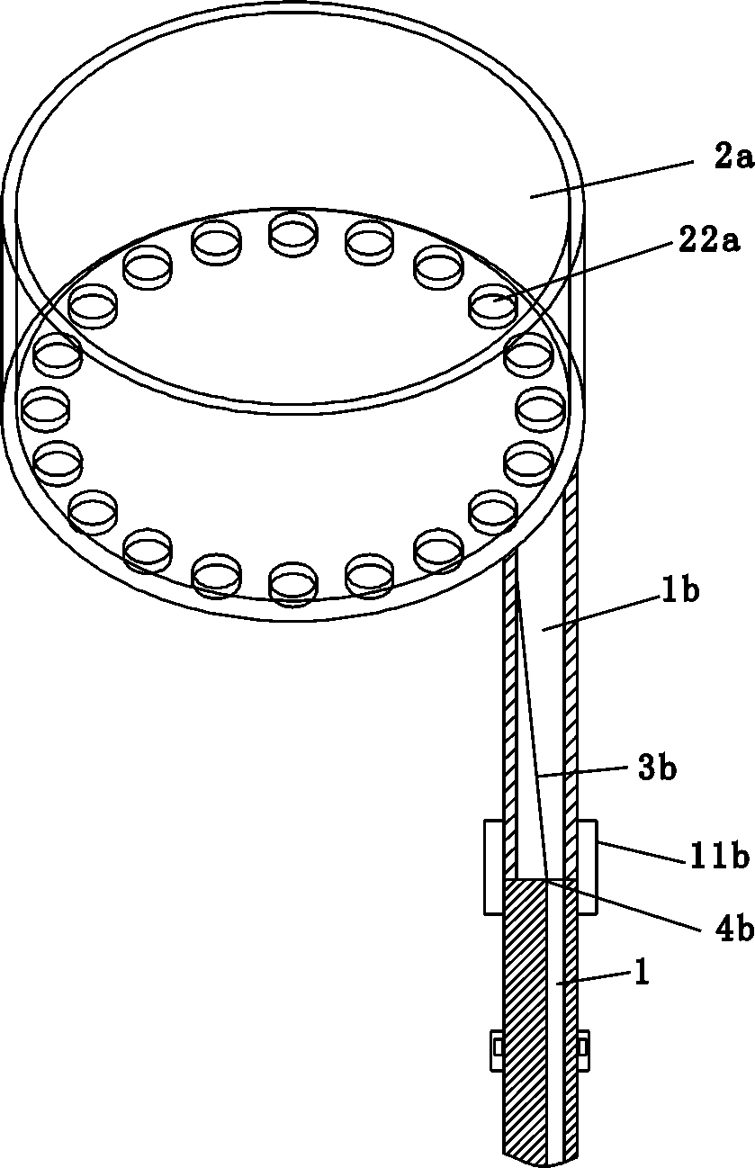
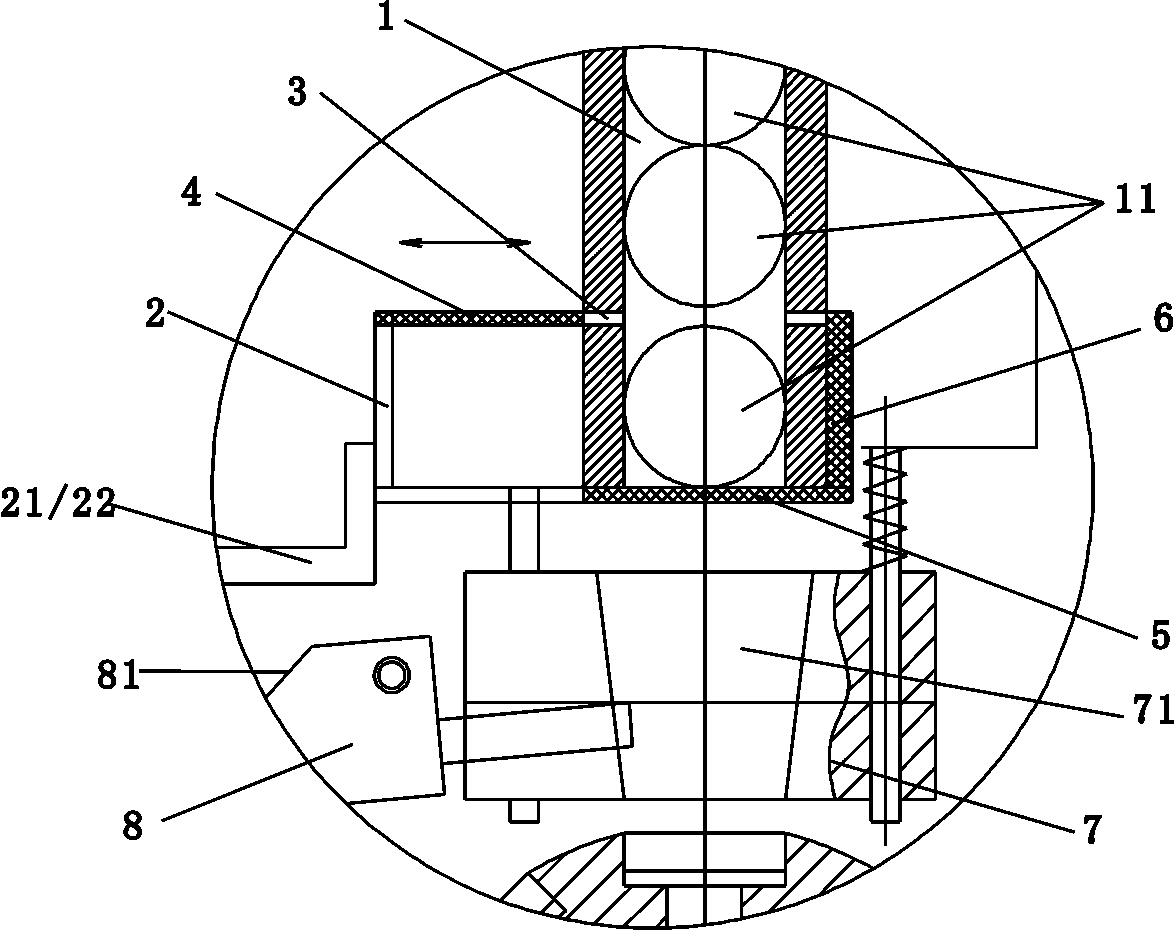
[0029] see Figure 1-11 , this implementation case includes:

[0030] Step 1: Inject the spar 11 into the delivery pipe provided with the slope 3b for orientation.

[0031] Step 2, set a gap rotation at the outlet end of the delivery pipe 1b, and set a carrier disc 1c or a carrier belt on the outer periphery for carrying the spar carrying hole 2c, and the oriented spar 11 falls one by one from the outlet end of the delivery pipe 1b into the exactly aligned In the loading hole 2c.

[0032] Step 3: The carrier plate 1c or the carrier tape rotating in the gap rotates to the delivery mechanism 4c located at the appropriate place below, the spar 11 falls or drives the spar 11 to fall into the corresponding position of the delivery mechanism, and passes through the clamping mouth of the delivery mechanism 4c Hold and transport to the appropriate place.

[0033] A reciprocating and sliding transfer block 8 is arranged between the outlet end of the delivery pipe 1b and the carrier ...


PUM


Abstract

The invention discloses a spar conveying method. The spar conveying method comprises the following steps that 1, spars are injected into a conveying pipe with an inclined surface to be oriented; 2, acarrying plate or a carrying belt is arranged at the outlet end of the conveying pipe, wherein the carrying plate or the carrying belt rotates intermittently, the outer periphery of the carrying plateor the carrying belt is provided with carrying holes for carrying the spars, and the oriented spars fall into the right-aligned carrying holes one by one from the outlet end of the conveying pipe; and 3, the carrying plate or carrying belt rotating intermittently is rotated to a discharging mechanism located at the lower portion and an appropriate position, and then the spars fall into or are driven to fall into the corresponding position of the discharging mechanism, and are clamped and conveyed to a corresponding position through a clamping opening of the discharging mechanism. According tothe method, the oriented spars fall into the right-aligned carrying holes one by one from the outlet end of the conveying pipe, further, the carrying plate or carrying belt rotating intermittently isrotated to the discharging mechanism located at the lower portion and the appropriate position, then the spars fall into or are driven to fall into the corresponding position of the discharging mechanism, and are clamped and conveyed to the corresponding position through the clamping opening of the discharging mechanism, finally, the spars are conveyed to the corresponding position through the discharging mechanism, so that the spars are continuously and accurately conveyed.

Description

technical field [0001] The invention discloses a crystal stone feeding method. Background technique [0002] Due to its beautiful appearance, spar has been widely used in fabrics. However, most of the existing spars are manually loaded or picked up by manipulators on the corresponding discs. During the use of spars, it is often necessary to accurately, continuously and stably transport a specific number of spars, and the existing equipment cannot meet this requirement. need. Contents of the invention [0003] In order to solve the problems existing in the use of the prior art, the present invention provides a feeding method capable of continuously, rapidly and accurately conveying a corresponding amount of spar. [0004] The technical solution of the present invention to solve the existing problems is: a spar feeding method, the steps are as follows, step 1, the spar is injected into a delivery pipe provided with an inclined plane for orientation. Step 2: Set a gap rota...

Claims


Application Information

Patent Timeline
Patent Type & Authority Applications(China)
IPC IPC(8): B65G47/04B65G47/88
CPCB65G47/04B65G47/8807
Inventor 陈镇杆
Owner ZHEJIANG HEHE ELECTROMECHANICAL CO LTD
Learn More